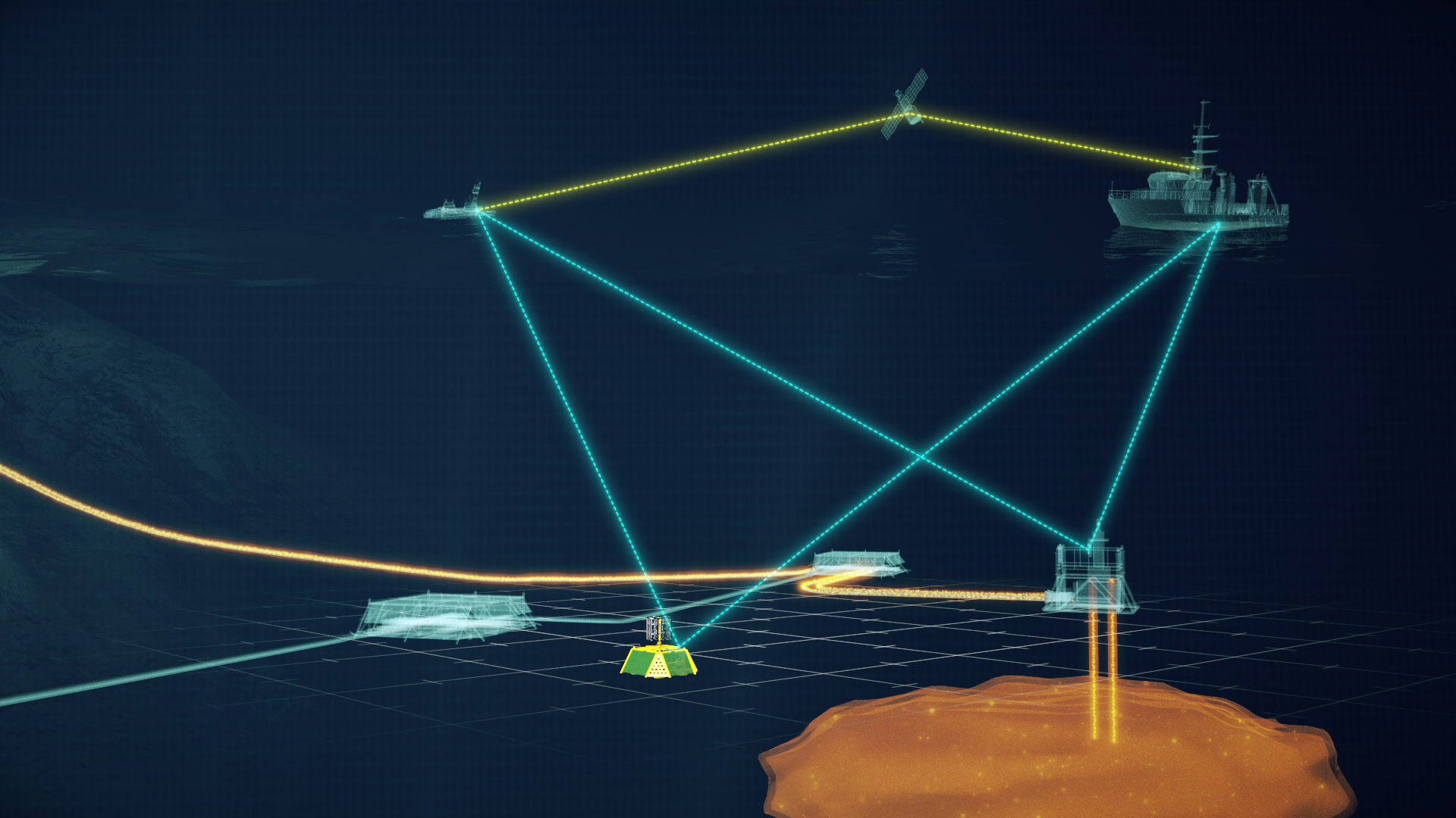
As we discussed in our first blog, offshore carbon capture and storage (CCS) has emerged as a promising technology to help reduce carbon dioxide (CO2) emissions in an effort to combat climate change.
Offshore CCS offers great potential for storing large quantities of CO2 in redundant oil and gas wells or saline aquifers deep beneath our seas. However, this process comes with the crucial responsibility of ensuring the integrity and safety of these geological storage sites. In this our second blog, we’ll explore the importance and challenges of comprehensive monitoring for offshore CCS sites and the technologies used to ensure successful storage.
Identifying Key Monitoring Locations
Monitoring CO2 in a subsea environment involves a tricky combination of physical oceanography, chemistry and marine biology. The starting point is that CO2 dissolves rapidly in water, typically within two to three metres of any escape, making direct measurement insufficient for effective monitoring. This, alongside other challenges such as mixing due to currents and tidal effects plus seasonal variations of other important in-water indicators, demands a multi-pronged approach to detection and monitoring.
To establish an effective subsea monitoring strategy, it’s crucial to first identify the areas requiring close observation. These may include:
- Higher risk areas, such as around the injection wellheads
- Known geological pathways through the substratum like faults, chimneys or reservoir boundaries
- Manmade subsea infrastructure (e.g., transport pipelines, flange points, manifolds, end terminations, etc.)
The Complexity of Subsea CO2 Monitoring
Effective monitoring of subsea CCS sites involves two critical phases:
Baseline Phase Monitoring:
This initial phase is essential to understand the natural, seasonal and daily variations of certain properties in the water column that could help explain fluctuations in naturally occurring CO2 levels, or other indicator properties, at the key locations. These other indicator properties are discussed below, but baseline monitoring needs to take place before the injection phase begins to establish a record of what is ‘normal’ to help identify any future anomalies.
Ideally, this baseline phase lasts for a full 12 months prior to the commencement of any CO2 injection.
Injection Phase Monitoring:
Once the CO2 injection process begins, continuous monitoring becomes crucial to detect any potential breaches at the key locations.
Both phases require continuous, high-frequency data collection – ideally hourly samples everyday throughout the year – to accurately capture variations over both shorter, daily, and longer, seasonal, time periods. This level of detail is necessary to help distinguish between natural fluctuations and potential containment losses, whilst minimising false alarms and ensuring no significant escapes go undetected.
Advanced Technologies for Offshore CCS Monitoring
Sonardyne and our sister companies, Wavefront and EIVA, are at the forefront of technologies for subsea CCS projects. Several of our cutting-edge technologies can be employed to form a system-of-systems approach with the aim of remotely monitoring offshore CCS sites effectively. These include:
Chemical Landers
Our advanced standalone, battery-powered seabed landers can be used to continuously monitor critical water properties. They feature our Origin 600 ADCPs to monitor current speed and direction whilst incorporating data from third party sensors to measure changes in CO2, pH, nitrates, salinity and dissolved oxygen. Other optional sensors, such as hydrophones for sea mammal monitoring or micro-seismic devices can be incorporated as needed.
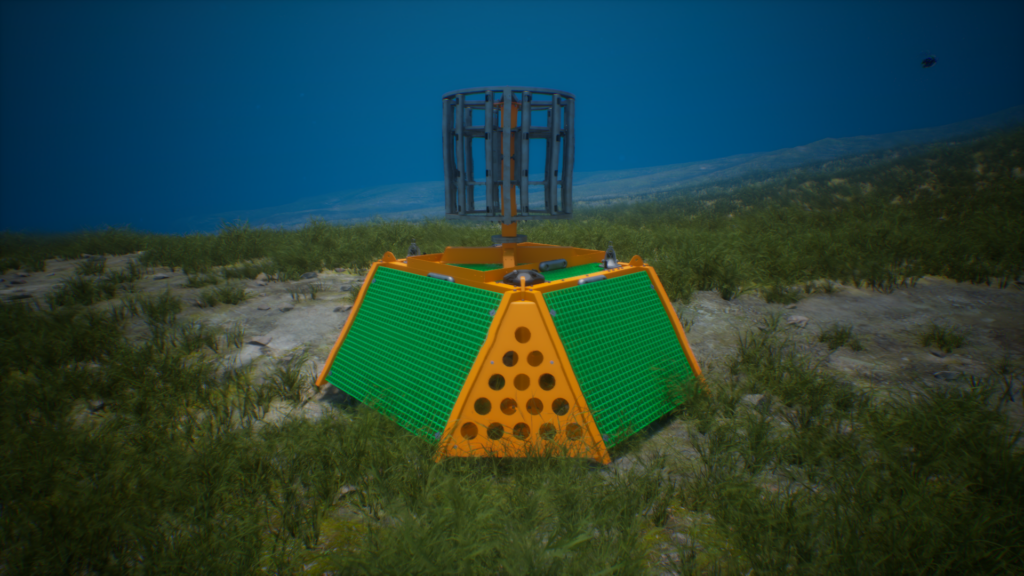
A generated image of a lander on the seabed
All these sensors are connected to a central processing hub (CPH) for secure data storage, sensor sample rate setting and local power distribution. Additionally, Sonardyne’s robust wireless through-water acoustic communications modem is connected to the CPH for both commissioning QC purposes and for gaining access to data during either the baseline or injection phases.
Advanced passive acoustic sonar technology from our sister company, Wavefront, can also be integrated with the chemical lander for enhanced detection capabilities, resulting in even smaller escapes being detected at longer ranges that the chemical analysis may miss.
Seabed Topography Monitoring
For seabed subsidence or deformation monitoring, our Fetch AZA logging nodes continuously check for any small changes in the seabed’s shape throughout the injection phase period, which could last for over 20 years. With our integrated acoustic communications package, recorded data can be sent to a topside vessel of opportunity, gateway buoy, uncrewed surface vehicle (USV) or autonomous underwater vehicle (AUV) on demand.
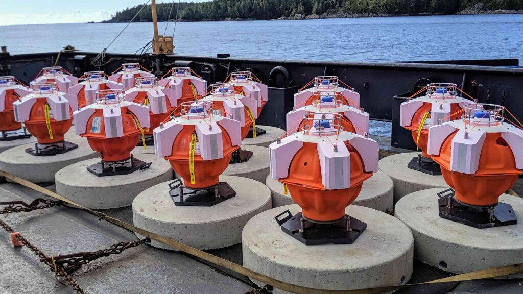
Fetch AZA nodes on a back deck waiting for deployment
Reservoir Plume Monitoring
Reservoir plume migration is monitored by deploying our acoustic data loggers connected to third party installed pressure and temperature gauges deep within the wellbore. This wireless communicating device can therefore remove the need to run a dedicated and expensive umbilical to an observation well to access this data. Variations in pressure and temperature over time can be recorded on these standalone, battery powered, devices. Much like our Fetch AZAs, data can be harvested at any time using a compatible transceiver integrated on a data harvesting vehicle of choice.
Active Sonar Technology
Complementing chemical sensors, and in addition to any passive acoustic sonar used, the Sentry active sonar system from Wavefront will create an acoustic base-map of a monitored circular area of around 2 km in diameter. By comparing these base-maps to real-time underwater scene observations created by Sentry, changes can be detected and emission alerts generated based on predefined threshold criteria.
Large Area Monitoring
In addition to the key location continuous monitoring techniques described above, there is also a requirement for reservoir extent, or large area, monitoring. To achieve this accurately, quickly and cost-effectively, our SPRINT-Nav inertial navigation systems have been integrated with EIVA’s Scanfish or Viperfish ROTVs and Wavefront’s Solstice Multi-Aperture Side Scan Sonar to provide high-resolution seabed surveys delivering a rapid containment assessment of extensive reservoir areas.
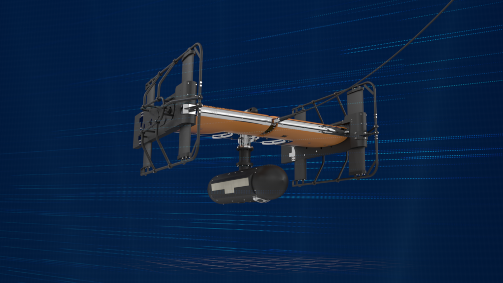
Generated image of a ROTV with sidescan sonar
This technology, coupled with Solstice’s automatic target recognition (ATR) of suspected leak anomalies, allows for efficient surveying of large areas and quick identification of inconsistent events that might indicate an escape.
Due to the lower risk of breaches away from critical locations, monitoring the larger expanses of the reservoir can be less frequent. Whilst locations around the injection sites and pipelines need continual monitoring, observation of the further boundaries may only need to be performed every three to five years.
Data Access and Analysis
Given the remote nature of offshore CCS sites plus the lack of power and communications for monitoring devices, data access is a critical factor of the site’s monitoring strategy. Thankfully, crewed vessels of opportunity or USVs equipped with our acoustic communication technologies can be used to retrieve data from all our subsea monitoring equipment.
Before transmission to the surface, the chemical lander’s raw sensor data collected by the CPH can be processed in-situ via its integrated Edge processing algorithms. This ensures that only relevant data is communicated via the acoustic modem, speeding up transmission times and reducing the need for post-processing onshore. Two-way communication via the CPH’s acoustic modem also enables mid-operation QC health-checks of the sensors and batteries, whilst also allowing any operational updates to be performed.
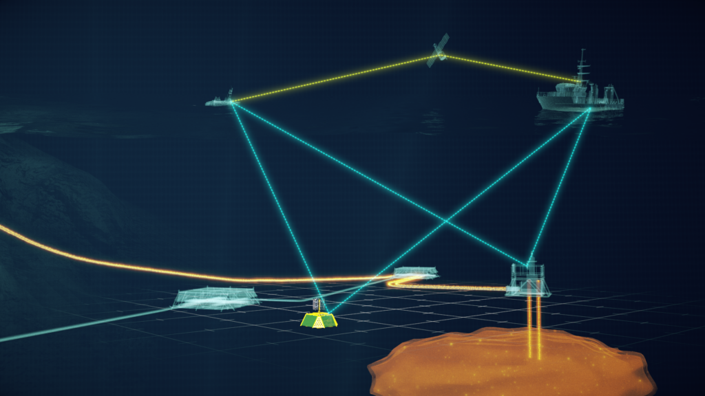
Generated image of a CCS monitoring network
Conclusion
Monitoring offshore carbon capture and storage sites is a complex but essential task in ensuring the effectiveness and safety of this climate change mitigation strategy. By employing the latest marine monitoring technology, as described above; to provide a combination of continuous localised monitoring at higher risk locations and periodic large-scale surveys of the entire reservoir extent, we can build a comprehensive picture of the storage site’s integrity.
As we continue to develop and refine these monitoring techniques, we take crucial steps towards making subsea carbon capture and storage a reliable and trustworthy tool in the fight against climate change.
In our third and final blog, we will consider the solution for the effective monitoring of offshore CCS sites.
Stephen Auld
Blog 1 – Carbon capture and storage a critical component of climate change mitigation
Blog 3 – Revolutionising carbon capture and storage monitoring Sonardyne’s cutting-edge approach
