Overview
Small in size, mighty in performance
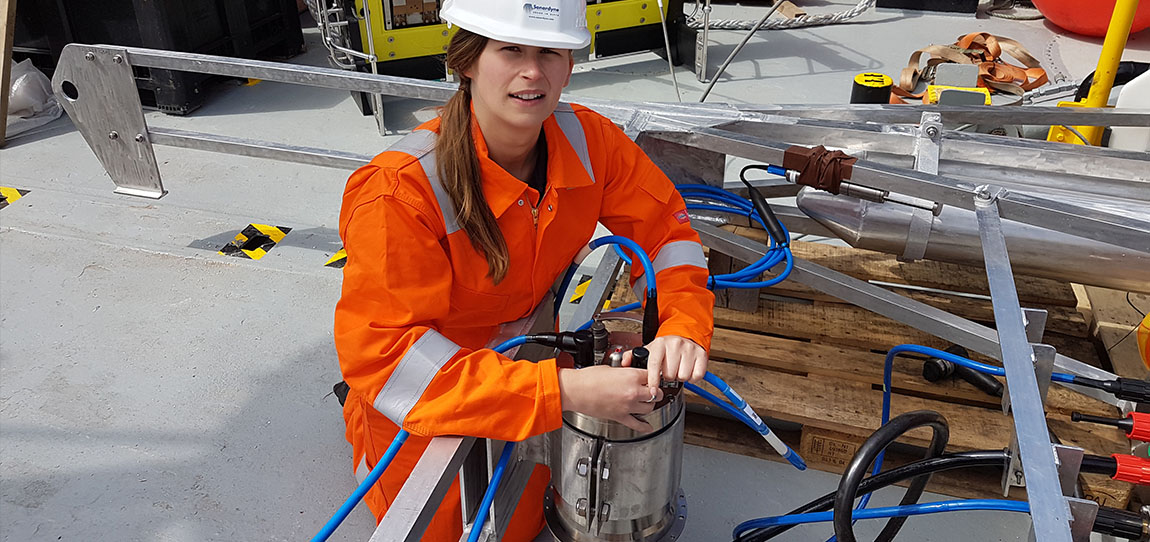
The class-leading capabilities and performance of SPRINT-Nav navigators are now available for all your marine robotic operations, no matter the size of your platform.
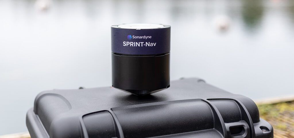
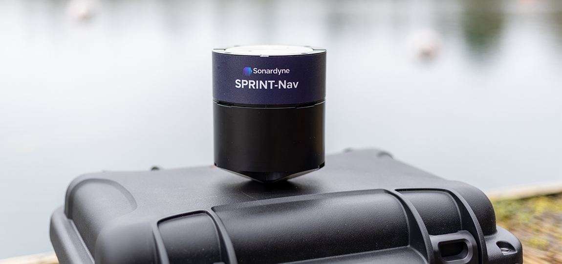
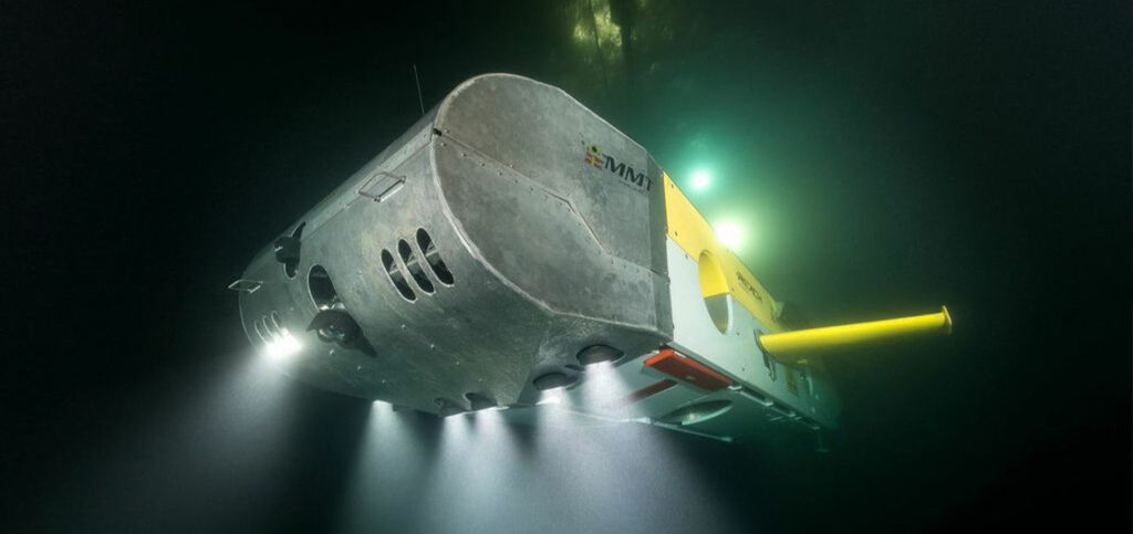
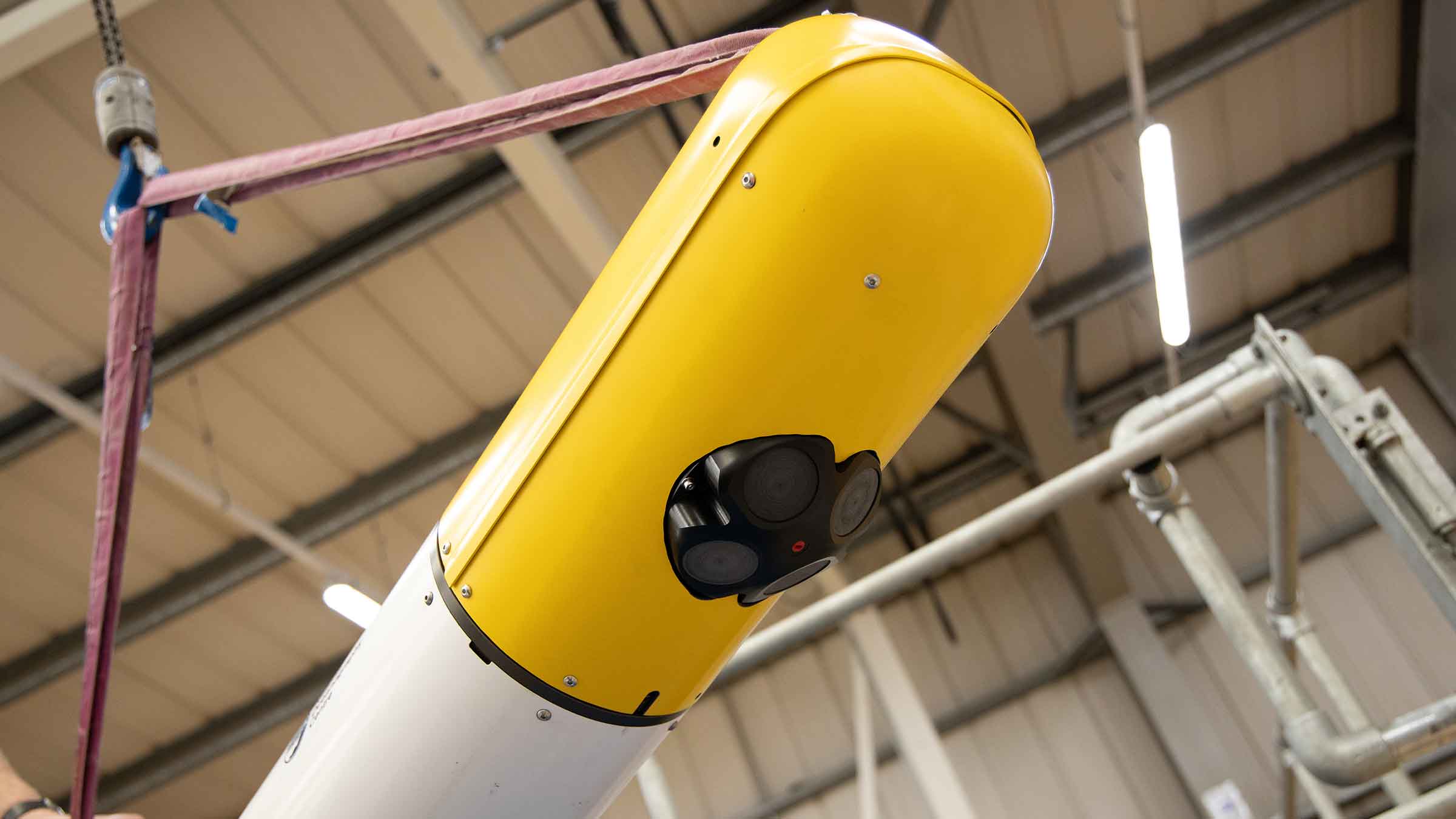
Designed from over a decade’s experience gained across the SPRINT-Nav family of products, SPRINT-Nav U is the world’s smallest hybrid acoustic-inertial navigator. SPRINT-Nav U has been designed to address a clear market need for smaller platforms to provide accurate, precise and robust guidance and navigation.
Find out what's possible
As with all SPRINT-Nav products, SPRINT-Nav U fuses AHRS, DVL, INS and depth data. All of this is now available in a single, ultra-compact and lightweight instrument giving you fast, precise and robust navigation, guidance and control information.
SPRINT-Nav U surpasses expectations in every way. With fast alignment, one unit, one connector, one cable and all the true-north seeking capabilities found across the SPRINT-Nav Family.
Game changing new capabilities for small robotic operations
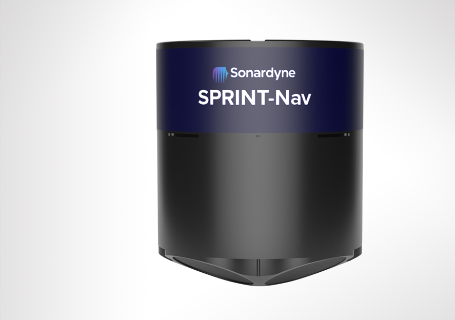
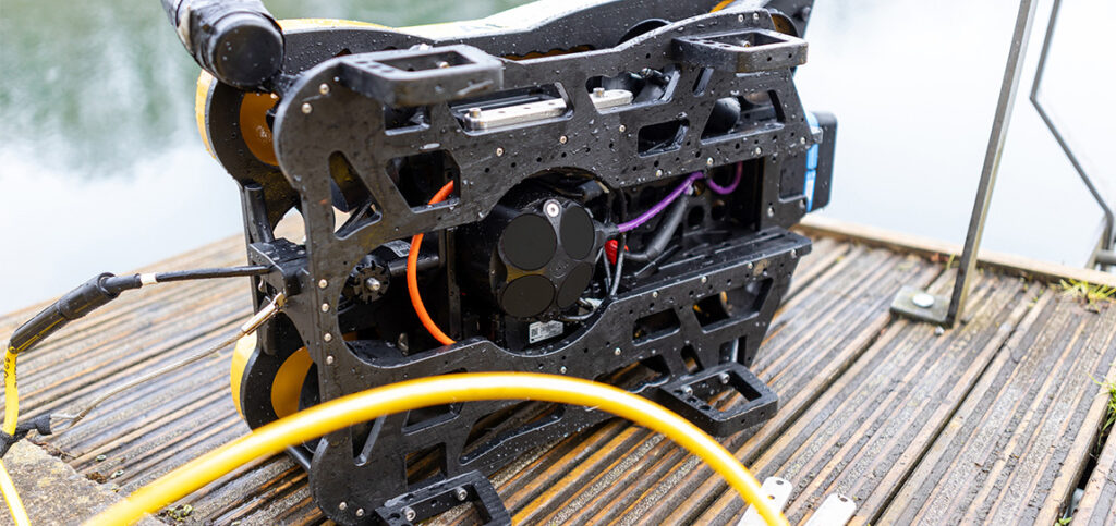
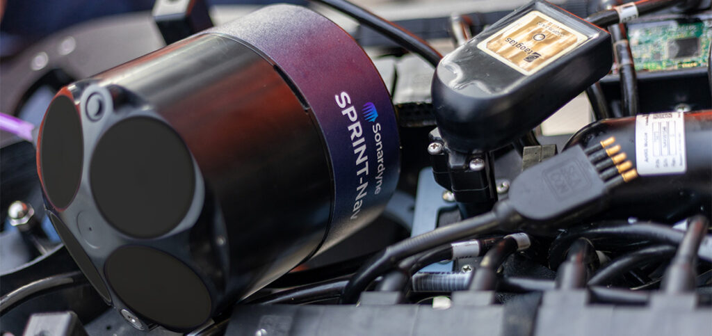
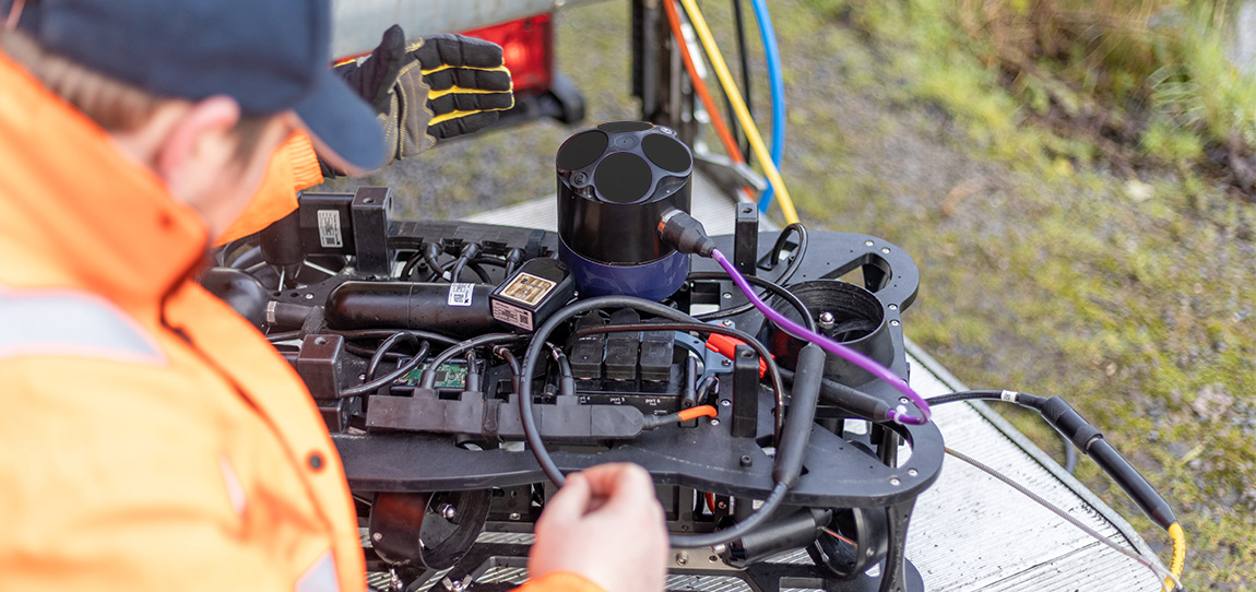
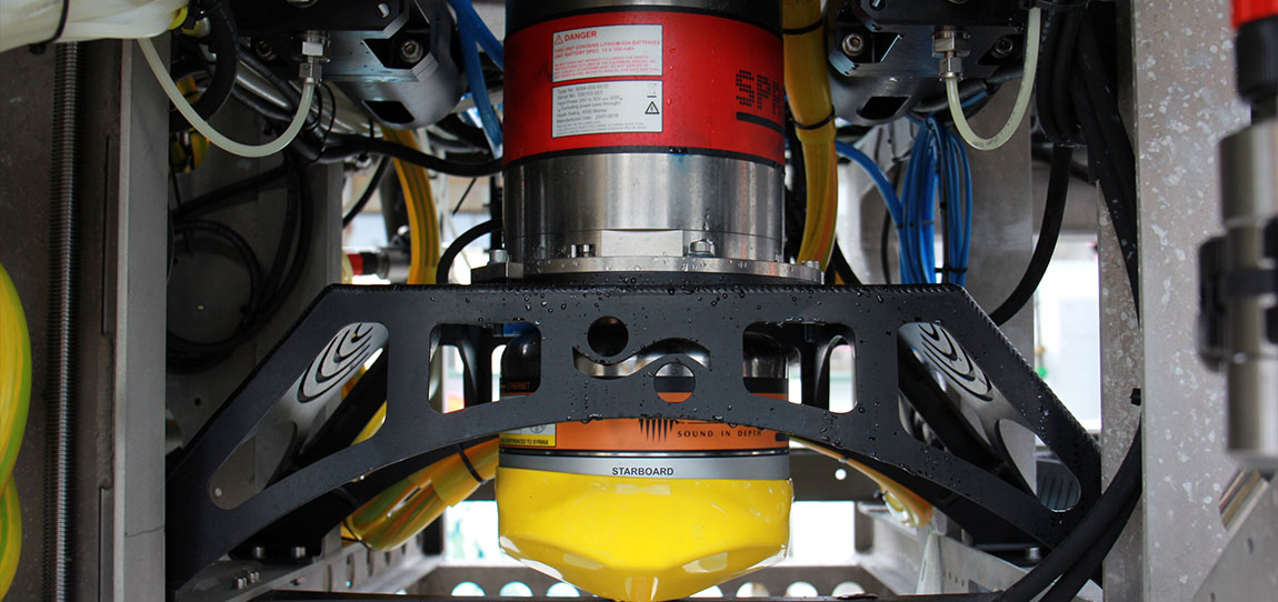
Measuring just 134 mm in height and 114 mm in diameter and weighing a mere 600 grams in water, SPRINT-Nav U packs full SPRINT-Nav capability into the space traditionally filled by just a DVL on small subsea robotic platforms. With its compact fibre optic gyro (FOG) Inertial Measurement Unit (IMU) SPRINT-Nav U is a game changer for small vehicle operations.
It’s powered by the same trusted hybrid acoustic-inertial navigation algorithm you’ll find across the whole SPRINT-Nav family. This combines the strengths of all its sensors to provide robust, precise and accurate outputs. SPRINT-Nav U continues to work even in ferrous environments where Micro-Electro-Mechanical Systems (MEMS) based navigation, with its magnetic heading, struggles. This means your operations are provided with a continuous stream of positions, orientation, velocities, depth and altitude even when operating in and around infrastructure.
Ready, set, go
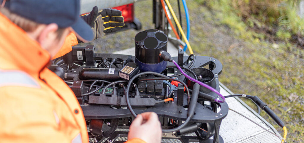
Your SPRINT-Nav U arrives pre-calibrated, meaning there is no need to spend valuable time conducting in-field calibration manoeuvres every time a vehicle is mobilised. It’s the fastest aligning subsea navigator available in the market. Arrive on site, turn it on, give it a position and away you go.
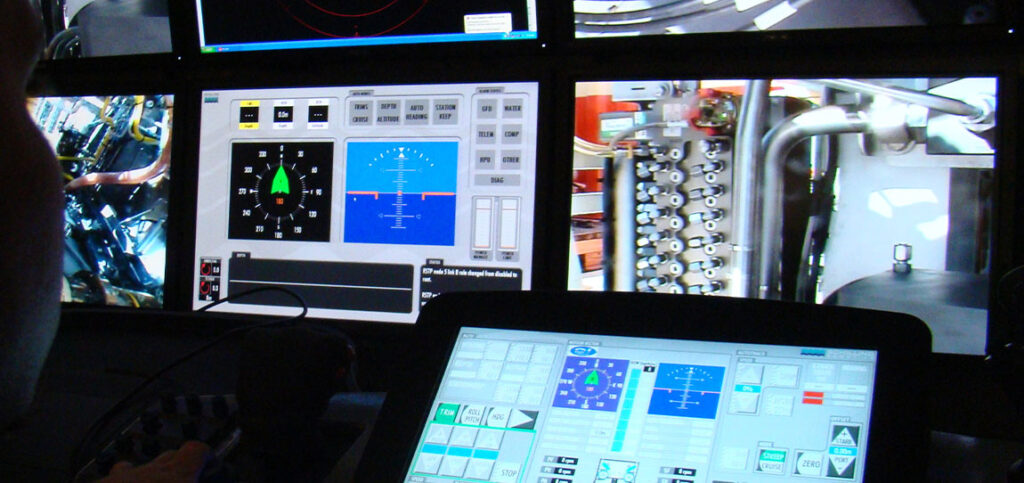
SPRINT-Nav U uses the same, familiar and simple web user interface as the SPRINT-Nav Mini, meaning its already user tested, field proven and has ease of use built in. As is standard for SPRINT-Nav products, the output can be fed directly to your own (or a third party) user interface or vehicle control software.
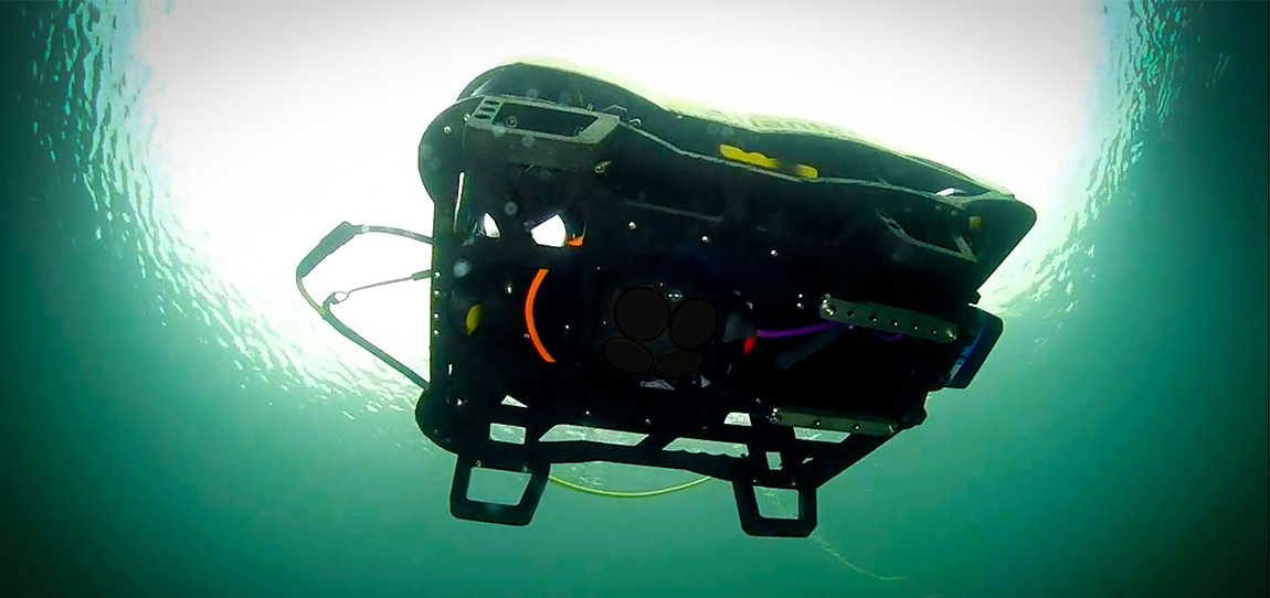
Need to do an ROV inspection of your offshore energy structures or ports and harbour infrastructure without deploying a large-scale vessel? SPRINT-Nav U will ensure accurate and continuous survey grade navigational data that is unaffected by the materials in such structures.
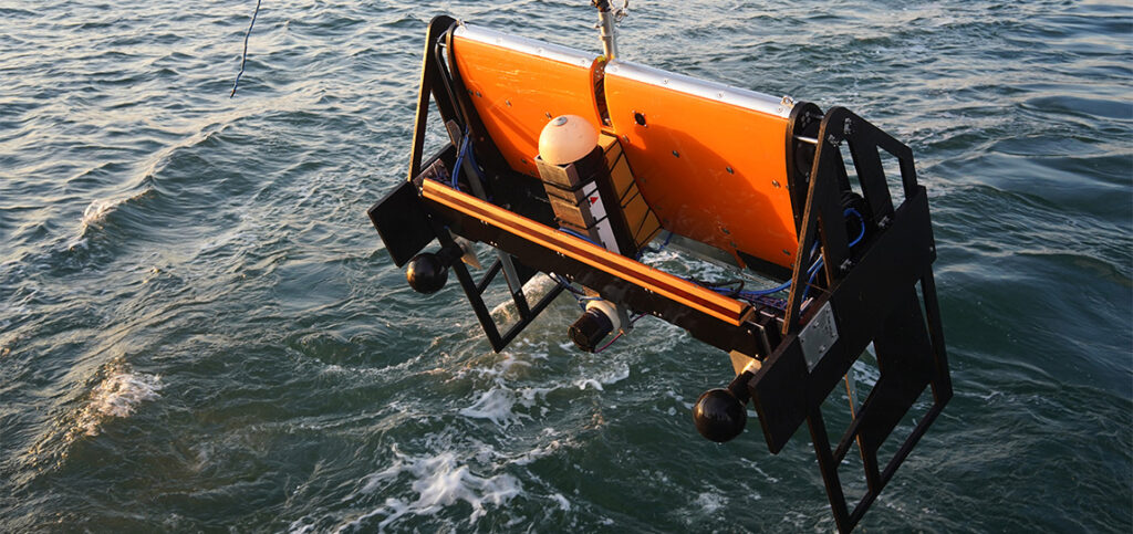
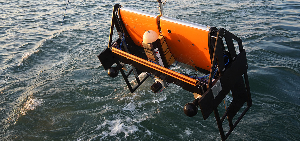
Conducting a seabed survey with your small AUV, Towfish or USV? No longer worry about the quality of the data you’ll get back as SPRINT-Nav U provides unparalleled navigational inputs for GNSS denied small vehicles and their payload sensors for accurate data collection every time.
Carrying out multiple surveys across a wide area? SPRINT-Nav U’s compact size and weight make it easily man-portable, deployable and retrievable from the back deck of a larger vessel.
SPRINT-Nav U at a glance
- 134 mm tall by 114 mm in diameter; the industry’s smallest all-in-one hybrid acoustic-inertial subsea navigator
- Compact hybrid DVL-INS synergies dramatically improve both robustness and performance compared with standalone instruments.
- Fly higher – 500 kHz DVL maintains bottom lock at up to 100 m altitude
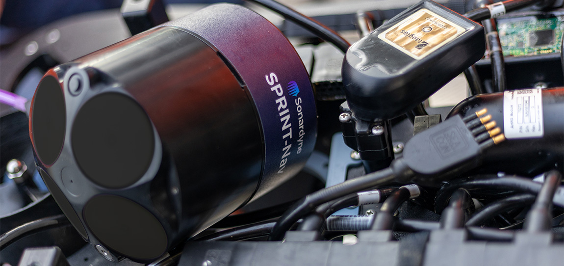
- Four instruments in one small package; AHRS, DVL, INS and pressure sensor – huge capability at optimised cost, size, weight and power (CSWaP)
- Easy to integrate, simple to operate, web UI for configuration


Discover SPRINT-Nav U in action
General
• Ideally suited for small subsea vehicle guidance, control and navigation
• Size, weight and power optimised
• Powered by our class-leading SPRINT hybrid navigation engine
• More compact and cost effective than the four separate sensors
• Gyrocompass simplicity with hybrid acoustic-inertial navigation performance
• Unaffected by proximity to ferrous objects
• Factory calibrated
Design
• Ultra-compact – 134 (H) x 114 (Dia) mm
• 1.98kg weight in air, 0.6kg weight in water
• Water-blocked cable
• Subconn micro circular connector (8-way female)
• Acetal copolymer 300m depth-rated housing
Performance
• True north seeking
• Provides 0.1% error for distance travelled (typical survey)
• Heading accuracy 0.15° secant latitude
• 0.02° pitch/roll accuracy
• 0.3/100 m min/max altitude
• Fast alignment
Ownership
• What’s in the box: SPRINT-Nav U
• Warranty: 1 year return to Sonardyne service centre
• ITAR controlled: No
• UK export licence: Yes
Specifications Table
| Performance | SPRINT-Nav U | |
|---|---|---|
| DVL aided | Typical survey | 0.1% |
| Distance from origin | 0.45% | |
| Altitude min/max | 0.3/100 m | |
| USBL and DVL aided | Precision improvement | Up to 4x |
| Heading (secant latitude) with GNSS or USBL, and DVL | 0.15 | |
| Heading (secant latitude) with GNSS or USBL or DVL | 0.2 | |
| Roll and pitch | 0.02 | |
| Angular rate range | ±450/s | |
| Velocity precision (<2 m/s at 50 m altitude) | <1.0 cm/s | |
| Depth accuracy | 0.01% FS | |
| Power | ||
| Power requirements | 24 V dc ±10%, 8 W nominal | |
| Physical/Comms | ||
| Data storage | 32 GB internal memory | |
| Serial ports/protocol | 1 RS232 (available on cable but not Subconn MCIL8F) | |
| Interfaces | Ethernet, UDP/TCP, WebUI, 1 x trigger inputs/output (1PPS in/out or DVL trigger), NTP, ZDA out | |
| Mechanical construction | POM-C, titanium | |
| Dimensions (diameter x height) | 134 x 114 mm (excluding penetrator) | |
| Weight air/water | 1.98/0.60kg | |
| Environmental | ||
| Depth rating | 300 m | |
| Operating temperature | -5 to 40 degrees Celsius | |
| Storage temperature | -25 to 70 degrees Celcius |
Frequently asked questions
Deployment
STP files
Software and firmware
Datasheets
DVL aiding – in the harshest environments
In pipeline inspection operations, for example, it’s preferable to get the vehicle as close to the seabed – and the pipeline it’s inspecting – as possible. But, this can cause the DVL’s bottom lock to be compromised, due to being too close to the seabed.
The challenge
For a number of operations, getting survey and positioning sensors as close to the seafloor as possible is important. However, this can lead to special requirements for sensor and vehicle design and an increase in operational complexity. Mounting the Doppler Velocity Log (DVL) with an unobstructed downward view, to achieve bottom lock, can become particularly difficult.
When operating ploughs or trenchers, most mounting options – eg. pointing the DVL directly towards the seabed, as is commonly done – compromises the DVL’s accuracy, due to the highly turbid water created by the vehicle it’s mounted on and the DVL beams being reflected or blocked by the trencher or plough itself.
One option, in these applications, is to separate the DVL from the inertial navigation system (INS). This allows more flexibility in terms of where the DVL is mounted. However, this can also adversely impact navigational accuracy, as it introduces lever arm and mounting angle errors between the INS and the DVL. Furthermore, performing DVL to INS calibrations are often impossible or very impractical on vehicles such as ploughs and trenchers, because vehicle manoeuvrability is not suitable for calibration purposes.
A solution for DVL mounting that improves flexibility on integration without compromising performance is required.


The solution
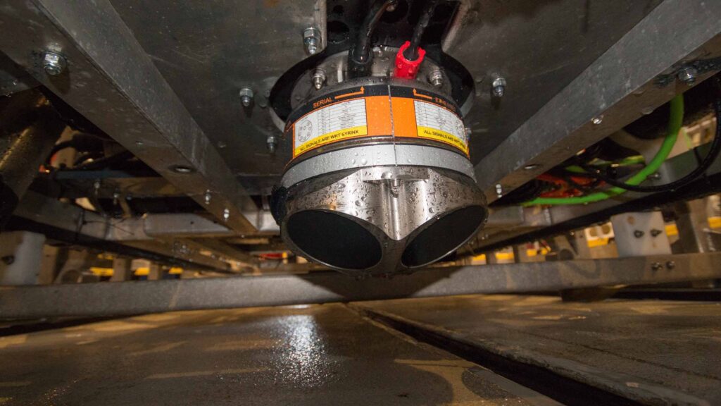
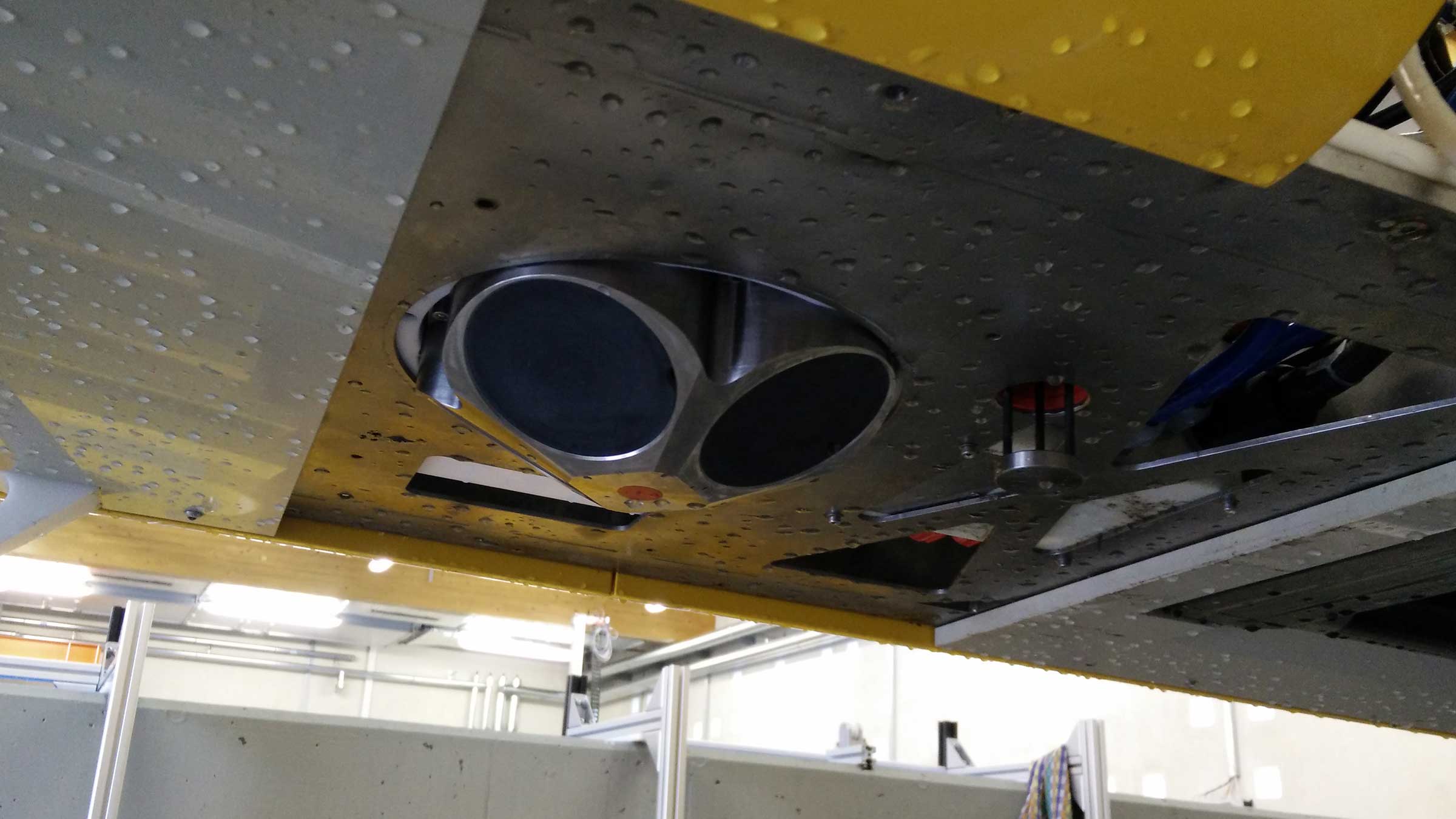
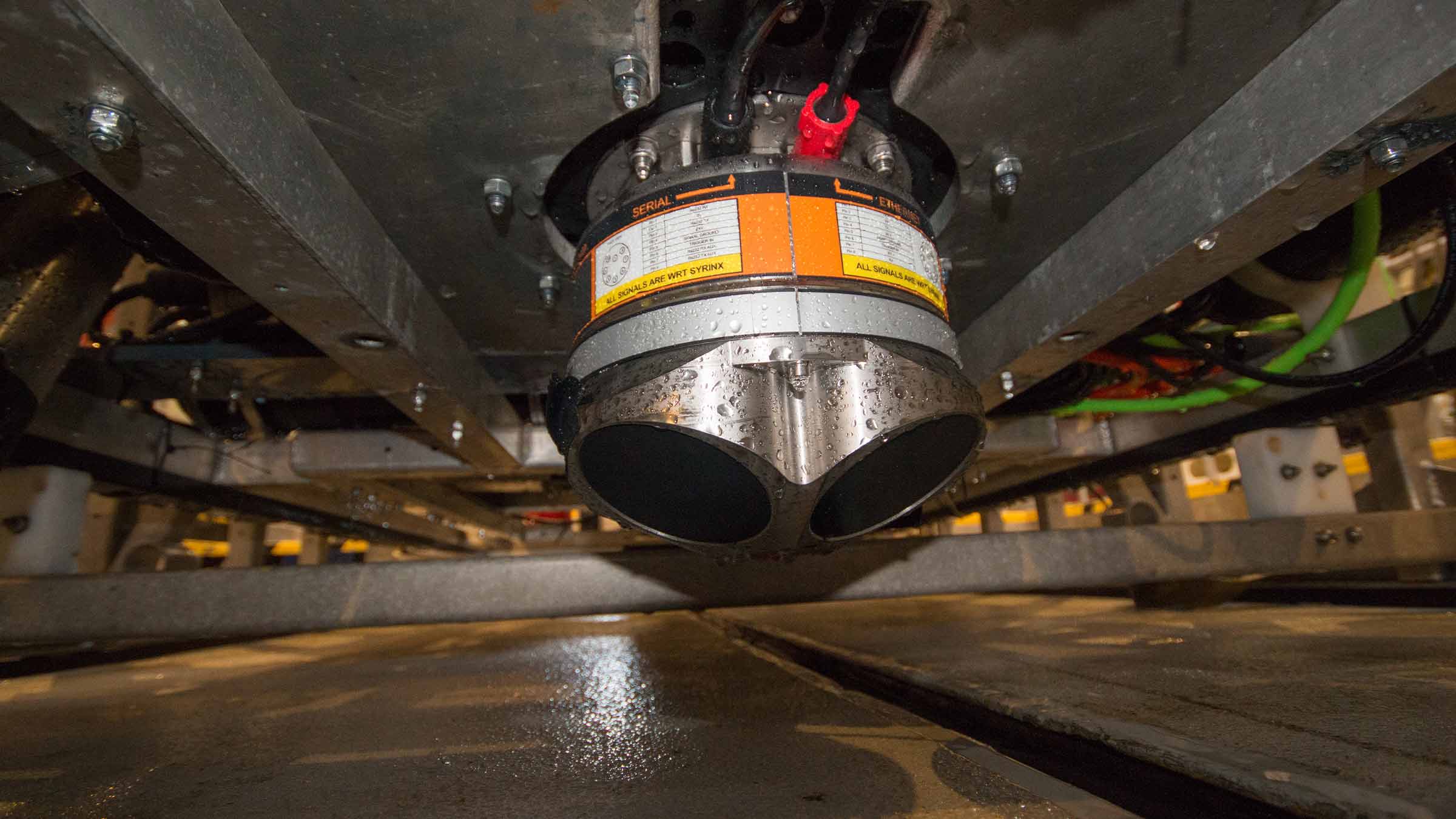
When mounting a DVL, one of the limitations is that optimal performance often requires vertical mounting. Our SPRINT-Nav – a compact INS and DVL in one – removes this limitation as it can be mounted at an angle. This avoids turbidity and the vehicle’s own infrastructure, which would otherwise interrupt its DVL beams.
The SPRINT-Nav can do this because the DVL it contains is tightly integrated at beam level. Each individual DVL beam is fed directly into the INS solution, instead of feeding in a 3D velocity solution that the DVL resolves by itself. This low-level integration means that SPRINT-Nav does not rely on the DVL alone for resolving a 3D velocity solution – it is handled more optimally by the INS. The SPRINT-Nav is then constrained and, critically, can be mounted at an angle, without compromising accuracy.
The idea of mounting the SPRINT-Nav at an angle was initially raised during a meeting with offshore survey solution provider UTEC. The concept instantly sparked great interest, as it had not previously been possible with existing INS solutions.
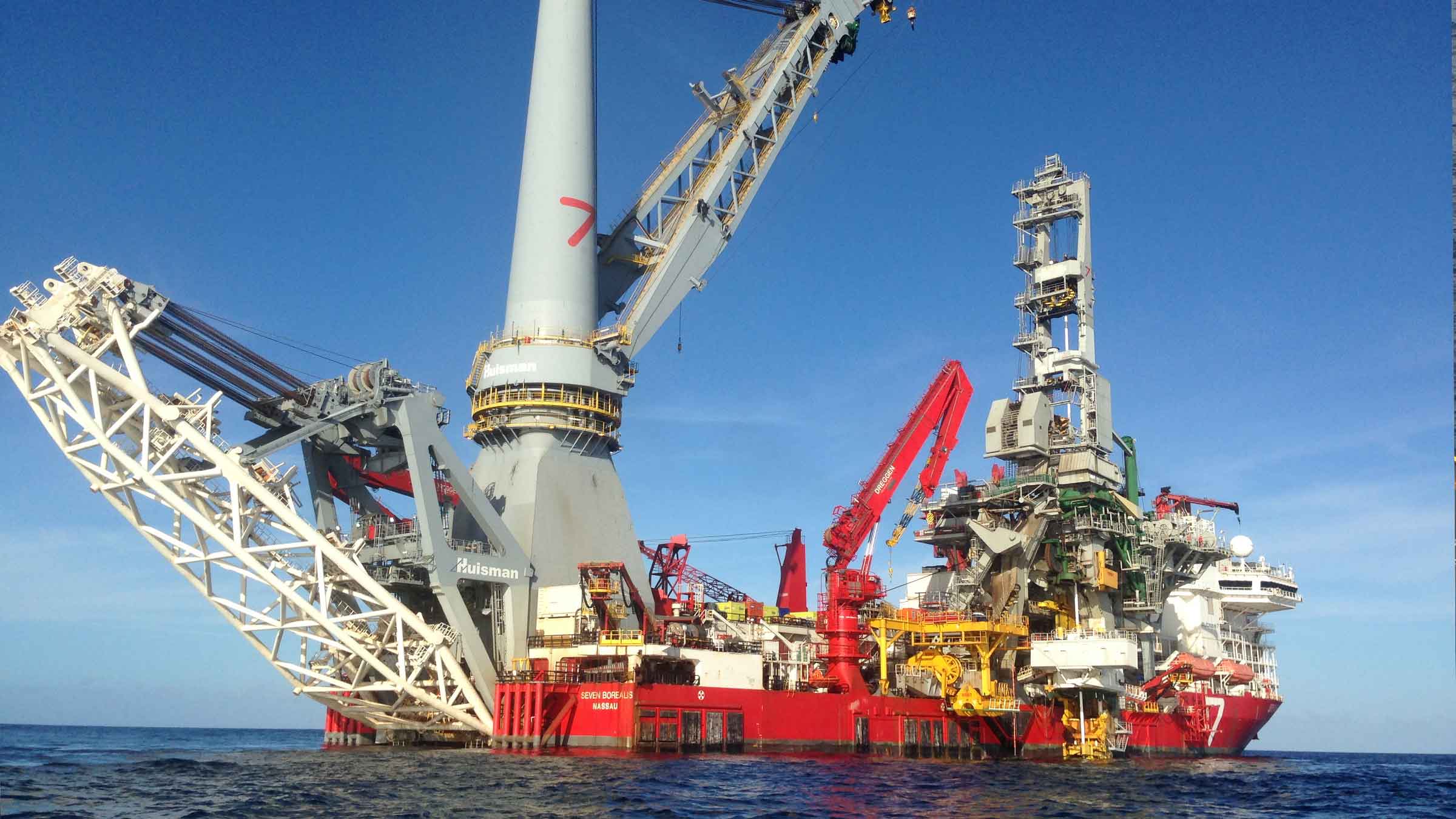
The next step was to test and evaluate how the alternative SPRINT-Nav mounting arrangement would perform for this specific application. The operation chosen for the evaluation was a cable lay project in the East Anglia ONE offshore wind farm, in the UK’s southern North Sea. There, UTEC was working from DeepOcean’s Maersk Connector cable lay vessel, providing positioning of DeepOcean’s plough during simultaneous lay and trench of a cable. UTEC’s objective was to get an accurate INS/DVL based position for the plough in order to replace the USBL positioning which had been degraded by acoustic noise from the vessel thrusters.
The project included both shallow and deeper water operations, with some very challenging conditions – highly turbid water, changing altitudes from the varying plough depth and sand waves and a very high level of vibration. Additional considerations included varying speeds as the plough made its way along the seabed and intermittent, noisy USBL updates from long layback tracking and vessel thrust.
All-in-all, it was a very tough application, in a very demanding environment. Both the inertial solution and the acoustics were thoroughly put through their paces. All the same, we were confident that SPRINT-Nav would perform well, despite the challenges it faced.
The ring laser gyro (RLG) technology used within SPRINT-Nav is almost immune to vibration; this is not the case for other competing gyro technologies. The tight beam-level DVL aiding increases robustness, so even if the DVL loses bottom track periodically or loses individual beams high levels of accuracy and reliability are maintained. What’s more, the pre-calibrated SPRINT-Nav does not rely on any additional calibrations or fine-tuning to ensure performance and the robustness of the SPRINT-Nav solution makes it less dependent on regular USBL updates.
This mounting arrangement had two benefits. Firstly, the SPRINT-Nav would always have four DVL beam returns as opposed to mounting it vertically, which would cause at least one of the beams to bounce off the plough’s infrastructure. Secondly, three out of four DVL beams would be directed away from the most turbid water surrounding the plough. This improves the signal-to-noise ratio and provides a more robust INS solution.
A bespoke mount was manufactured for this project. This enabled us to adjust pitch and yaw angles when needed during testing. Furthermore, post-processing in our Janus software was proposed to deliver the most accurate as-laid cable data.
The cable lay project was divided in three parts: integration and mobilisation; shallow water shake-down; and ploughing. A Sonardyne engineer was present for the initial shallow water shake-down and after a review of the integration, the system was deployed.
Throughout, SPRINT software was used to monitor the raw beam velocity data from the SPRINT-Nav’s integrated DVL. It became instantly obvious that all beams were achieving a good lock, even with the 30° pitch angle. It was also seen that the system continued to observe good data throughout the entire operation.
0
degree
angle of operation
SPRINT-Nav
0
m
depth rating
The results
Throughout both the shallow water and deeper water cable lay operations, the SPRINT-Nav performed well and no performance degradation from the 30° pitch angle mounting was experienced. On-board team members also found the topside software (SPRINT) intuitive and very useful for troubleshooting and tweaking the system.
As the environment was very new to Sonardyne (low speed, jerking motion, high turbidity), we also collected a lot of very useful data. This included DVL and INS data, which has helped us to understand how we can further improve the set up for these and similarly challenging applications.
We thank UTEC and DeepOcean for supporting this trial and look forward to providing this solution on future projects.
Ranger 2 – it's anything but standard
Carbon Capture and Storage is increasingly seen as one of the key measures to help us reduce greenhouse gas emissions. Capturing it is one thing, storing it and making sure it stays stored is another, which is why the National Oceanography Centre (NOC) and others have been working to understand the nature of potential CO₂ leaks and test sensor capability to detect these.
The challenge
Understanding how carbon dioxide behaves in deep water environments requires specialist equipment and multiple sensors. The various systems need to be able to work together smoothly, fly through the water without drag and reliably stay in contact with above water instrumentation.
One of the NOC’s most recent missions focused on CCS. As part of the European Union Horizon 2020-funded Strategies for Environmental Monitoring of Marine CCS (STEMM-CCS), it focused on CCS in the North Sea.


The solution
The project, involving researchers from Germany, Norway, Austria and the UK, and industry partner Shell, centred on the decommissioned Goldeneye field, about 100 km offshore Scotland in about 120 m water depth. In May 2019, researchers and scientists onboard the RRS James Cook set out for Goldeneye for an intense period of scientific activity.
The aim was to simulate carbon dioxide (CO₂) leaks from the seafloor in order to test various sensors and systems for their ability to detect potential CO₂ leakages. This would help the teams understand how the gas behaves, and discover if seepage from the seabed worked its way up through the water column.
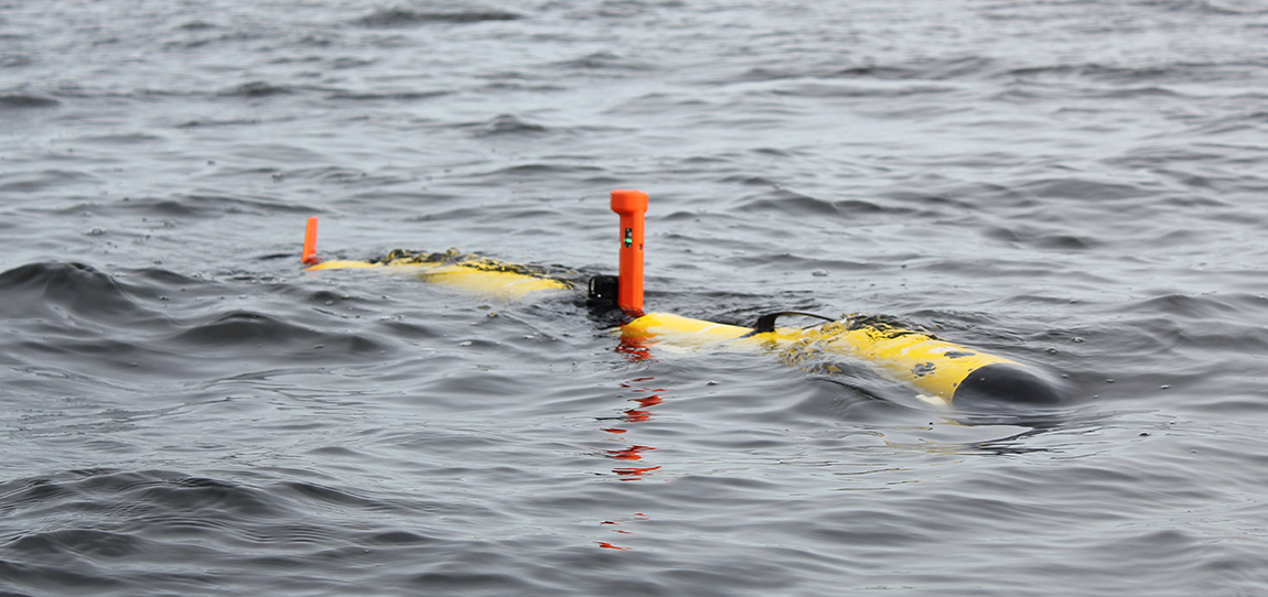
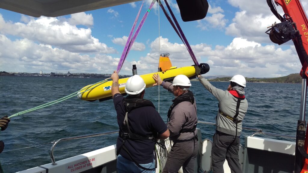
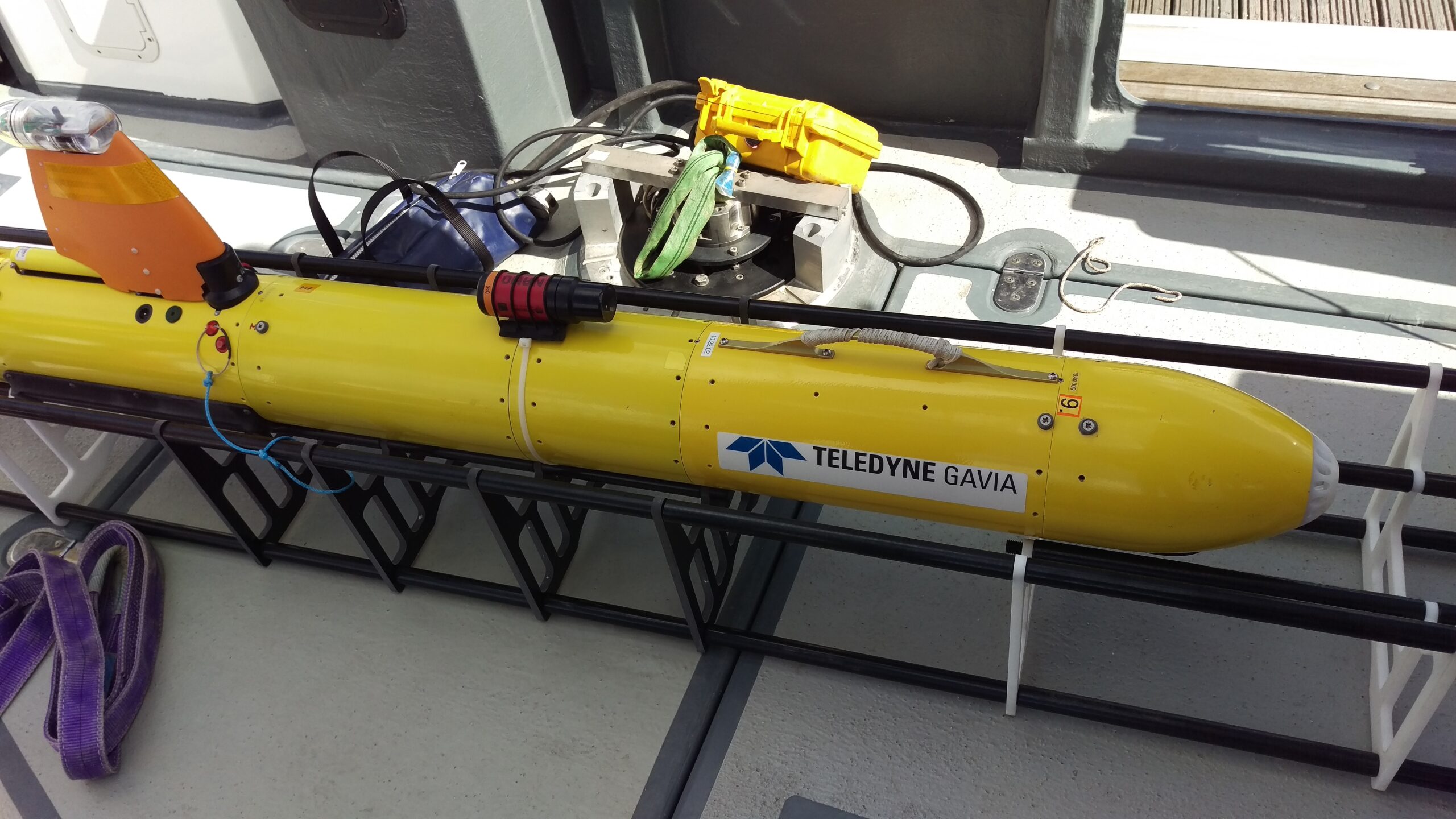
For mapping the area and wide-area chemical sensing, they used a Gavia autonomous underwater vehicle (AUV) called Freya. Because the Gavia had been adapted specifically for the mission – including fitting additional sensors to its body – operators were uncertain about how it would now fly through the water.
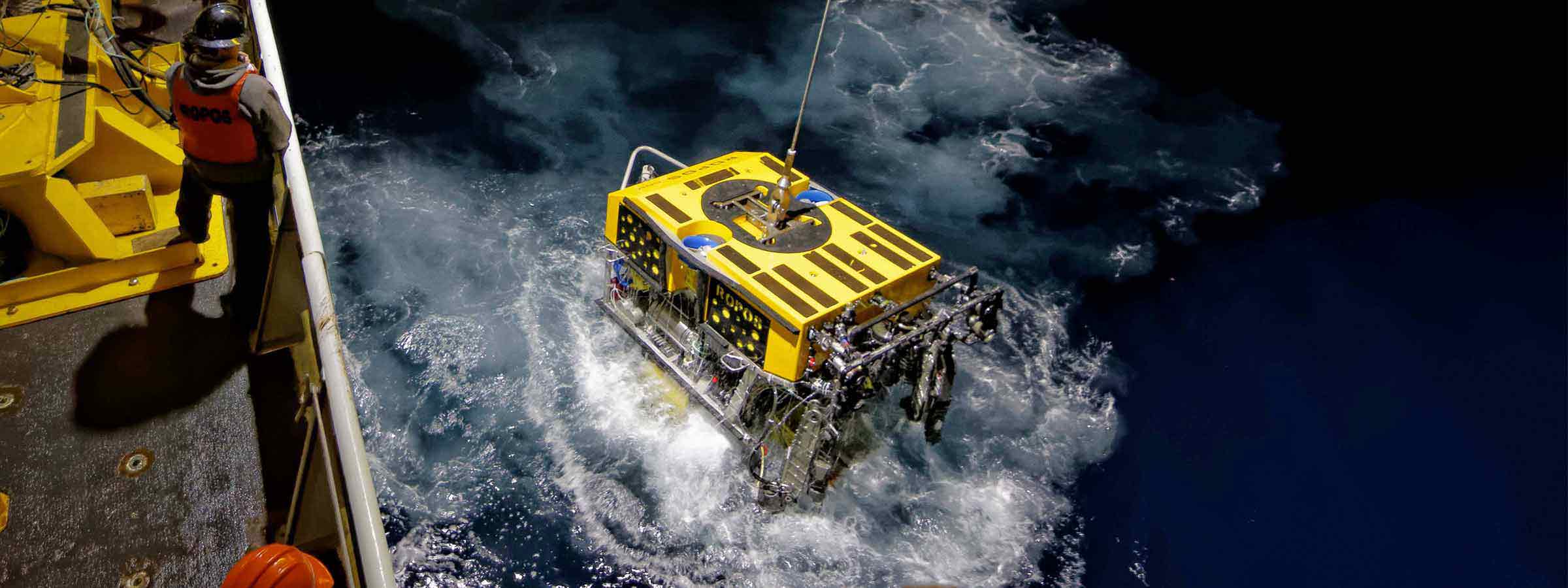
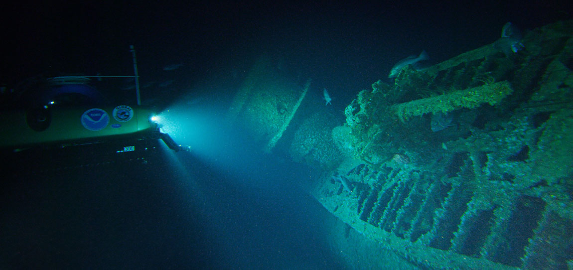
Our Ranger 2 system has underpinned the ocean science carried out by the RRS James Cook since it went into NOC service in 2006. It’s helped to track a whole host of vehicles and instruments, including NOC’s Isis ROV to 5,000 m deep. Indeed, on this latest mission, Isis, with a 6G Wideband Mini Transponder (WMT) onboard, was tracked using Ranger 2 during its many trips to the seafloor where it helped to accurately install an array of seabed equipment, sensors and instrumentation.
The Gavia Freya is classed as a low-logistics vehicle – meaning that only two people are required to deploy and recover it. Typically, Gavias measure anywhere between 1.8 m and 4.5 m in length, and just 200 mm in diameter. So when it came to choosing which USBL transponder to equip Freya with, there was really only one option Nano.
It’s our smallest 6G-enabled USBL transponder (just 160 mm tall by 52 mm diameter) and comes with features such as wireless charging, depth sensor and lightweight plastic construction. For this mission, Freya’s mission payload included a GeoSwath system for side scan sonar and bathymetry, mounted externally to the hull, supported by additional buoyancy. This provided a convenient place to the site the Nano. Freya was also used for photographic surveys and chemical sensing for pH using the SeaFET system.
For maximum operational flexibility, the RSS James Cook is permanently fitted with both our HPT 5000 (wide area) and HPT 7000 (deep water optimised) transceivers to separate, through-hull deployment spars. Whilst either of these medium frequency transceivers is capable of tracking a Nano, the shallow water at Goldeneye meant that the Gavia was tracked with the HPT 5000.
The results
“We were able to use the displays from the Ranger 2 to see that the Gavia was getting down to its working depth, usually around 100 m, as we were mapping the seabed,” says Mike Smart, Glider Engineer, Marine Autonomous and Robotic Systems, National Marine Facilities, NOC. “This was very useful as there was quite a lot of uncertainty about how the Gavia would behave given the extra payload it was carrying. Tracking data from Ranger was also shared across our network with survey and science teams elsewhere onboard.
“Being able to track the progress of the mission was another nice feature. With a much longer and heavier configuration of Gavia than we usually deploy, the time it needed to resurface was longer than we had predicted. So, being able to view the vehicle’s precise location, aided by regular depth updates from the Nano, meant we could more accurately predict surface times and not be anxiously waiting for Freya to reappear at the end of her survey run.”
This is just the latest time we’ve been involved in the work towards CCS. Past work demonstrates how our Sentry leak detection sonar and our Solstice side scan sonar are able to detect leaks, as static and dynamic sensors. Our instruments have also been shown to be able to support so-called chemical “sniffers” that can detect CO₂ (see Baselines 12 and 18).
While it’s still an emerging area, the industry is getting closer to making CCS offshore a reality – the first offshore carbon storage license was awarded in the UK in 2018, followed by a new license for a significant storage site in Norway in 2019.
Speak with one of our experts to learn how we can make your CCS project a success.
Recovering lost history with Mini-Ranger 2
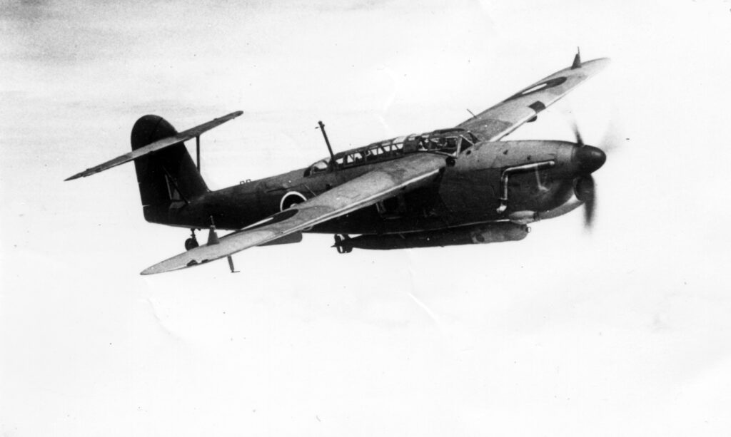
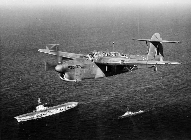
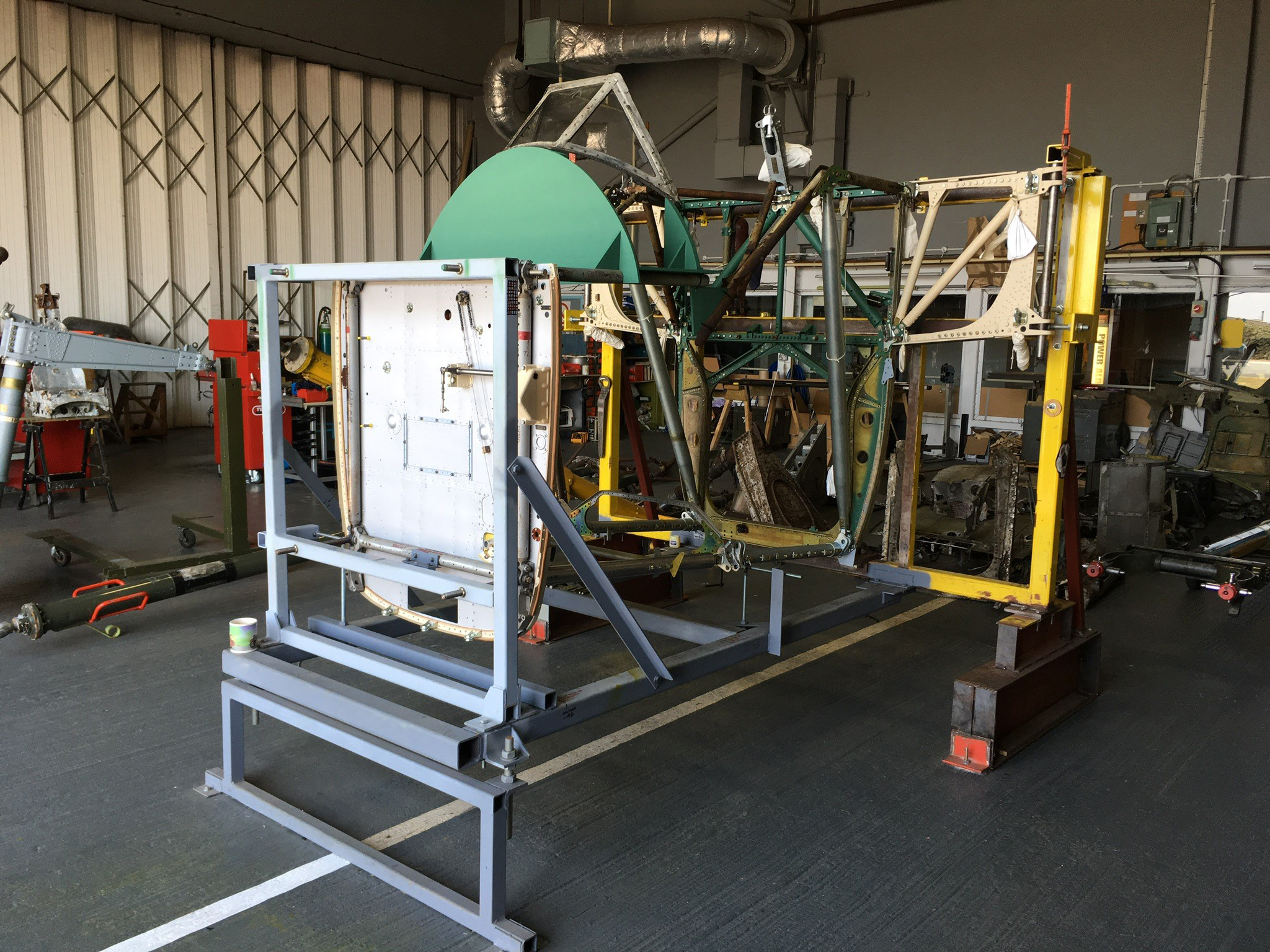
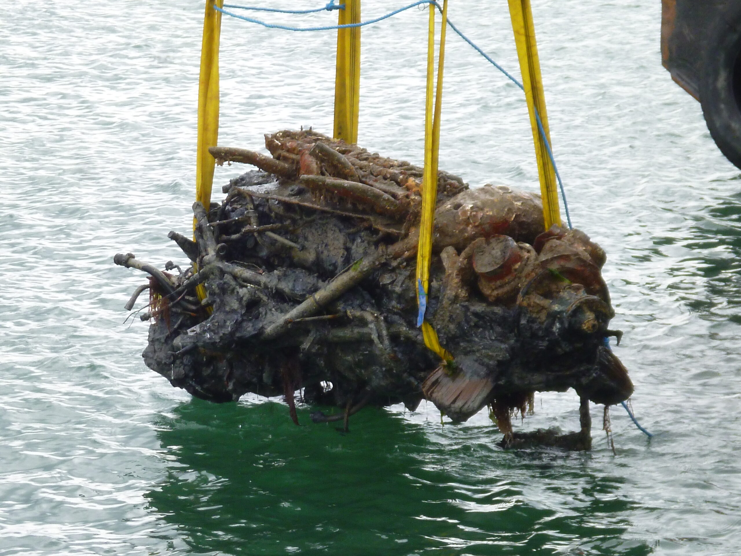
In its working life, there were more than 2,500 Fairey Barracudas delivered to the Royal Navy’s Fleet Air Arm. That’s more than any other type ordered by the Royal Navy to date. Read how James Fisher Marine Services used our Mini-Ranger 2 USBL system to recover this piece of World War II aviation history.
The challenge
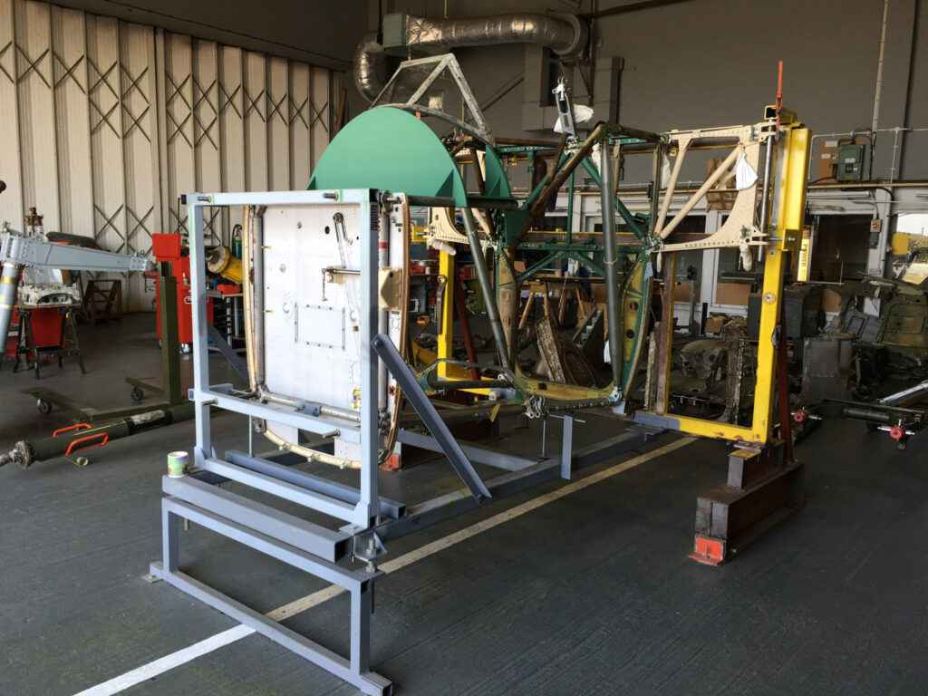
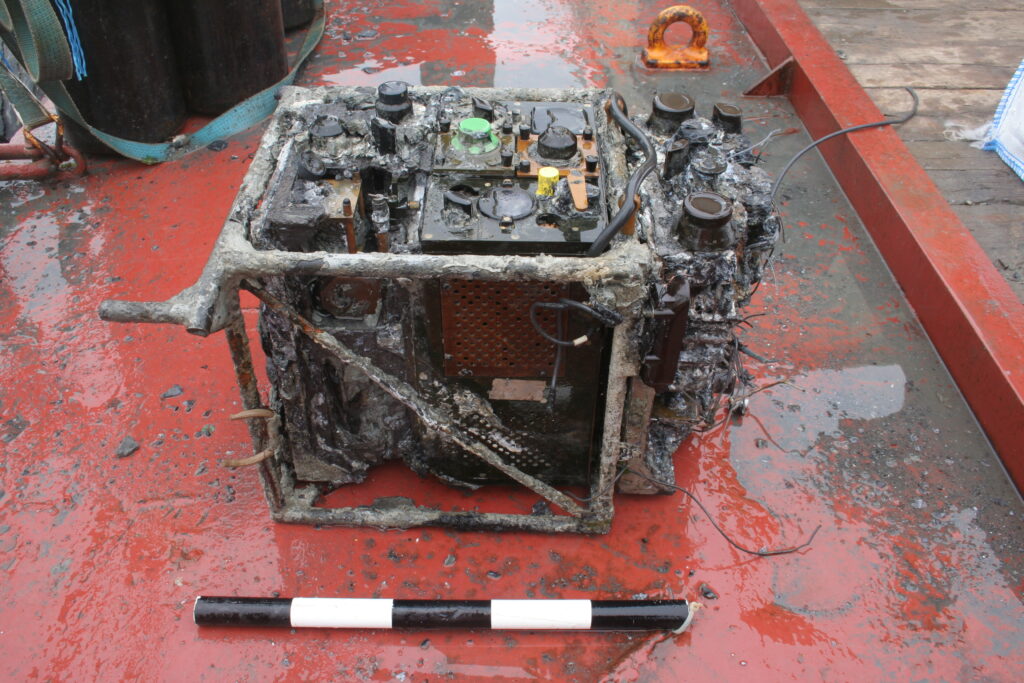
A three-seat, single engine torpedo bomber, it was launched from aircraft carrier decks during World War II, carrying their lethal load to drop on to targets. Despite the numbers that were built, none remain in the UK today, at least not in complete form. However, restoration engineers at the Fleet Air Arm Museum (FAAM) in Yeovilton are looking to change that and a chance find in the English Solent is helping them on their way.
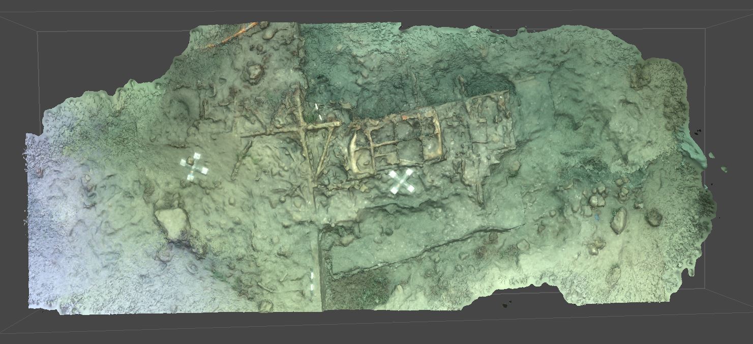
It’s the wreck of a Mk II Fairey Barracuda, discovered in 2018 by James Fisher Marine Services (JFMS) during a UXO survey for a new 204 km long power interconnector between the UK and France as part of the Interconnexion France-Angleterre 2 (IFA2) project.
IFA2 is National Grid’s second electricity subsea interconnector to France and is a joint venture with French System Operator RTE.
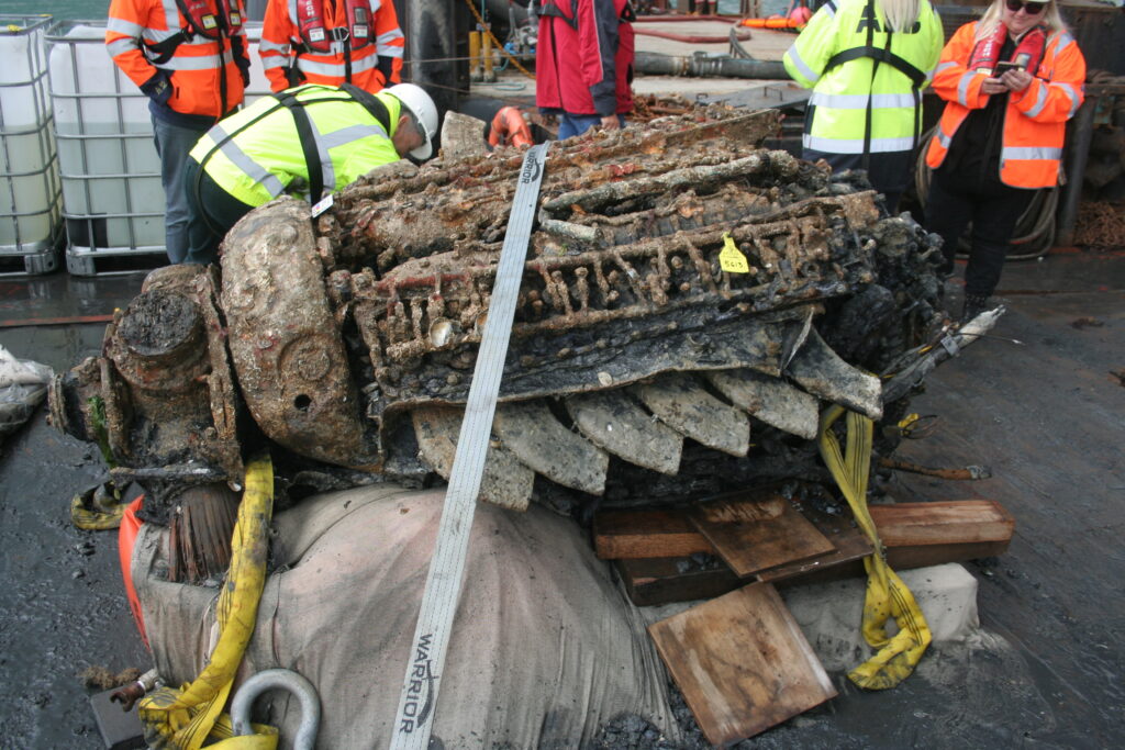
The wreck is believed to be one of two Barracuda aircraft which were based at Lee-On-Solent, Gosport. Both planes suffered forced landings in the Solent during WW2, shortly after take-off from HMS Daedalus airfield. While each pilot survived and made it through the remainder of WW2, their planes remained at rest on the seabed.
A challenging acoustic environment for USBL systems
Recovery of the wreck offered a great opportunity to the Fairey Barracuda restoration effort. But, it also posed a number of challenges, not least the water depth – or rather lack of it. Lying in just 5 m, Robin Fidler, who was then Survey Operations Manager at JFMS, expected to encounter acoustic interference problems tracking his divers due to signals bouncing off the seafloor and sea surface – often referred to as multipath.
Multipath can cause a USBL transceiver at the surface to falsely detect (or completely miss) a genuine reply signal from a transponder, leading to unstable tracking performance. Previous generation USBLs were particularly susceptible to multipath and needed careful setup to overcome the problem – not always successfully.


The solution
JFMS chose our Mini-Ranger 2 USBL system for the project. Mini-Ranger 2 is our mid-level USBL target tracking system. It provides shallow water performance without the cost and complexity of a deep water USBL solution. It’s also portable and quick to mobilise; a great choice for small survey vessels, moored barges and uncrewed vessels.
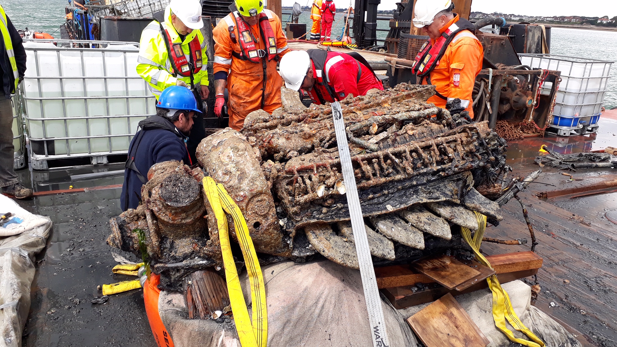
Six divers were used on the three-week project from the Stour jack up barge, with one diver in the water at any one time. The barge itself was fitted with an HPT 3000 transceiver mounted to the side, cabled back to a survey shack where the diving operations were controlled from.
WSM 6+ transponders fitted to each diver’s cylinder enabled the HPT to track every moment of their dive, providing a valuable layer of safety to the operation. Each diver also carried one of our Nano transponders in their pocket, this was used to place directly on top of any archaeological finds, so that precise waypoints for each artefact they discovered could be logged (and individually named) in the Mini-Ranger 2 USBL software. This information is then available for offline analysis.
The Mini-Ranger 2 USBL uses Wideband 2 for digital signal processing, so multipath never became an issue for the recovery operations, regardless of the depth of the tide. This had the additional benefit of freeing up users to deploy our USBLs virtually anywhere.
The results
The crash site was heavily silted so it needed to be cleared away for sections of the aircraft to be lifted out of the water. Artefacts retrieved included one of the pilot’s boots, a boost gauge and the underwing pitot head and mounting bracket – a delicate instrument that was used for recording the aircraft’s airspeed. The fact that this was found intact implies that the Barracuda was almost at stalling speed by the time it reached the water, says Wessex Archaeology’s Senior Project Manager Euan Mc Neill.
“We were really impressed with just how Mini-Ranger 2 operated,” says Fidler. “We thought we were going to have to use a (Fanbeam) laser radar system, tracking a reflective buoy attached to the diver to give us a range and bearing to the diver. We didn’t have to use it once; we could do it all with USBL, no matter what the tide, which made our lives much easier and that’s all we could ask. The USBL didn’t miss a beat. We were up and running with it quickly meaning that we were able to maximise the three week window we had on site.”
Optimising shallow water positioning for combined magnetometer and hydrographic surveys
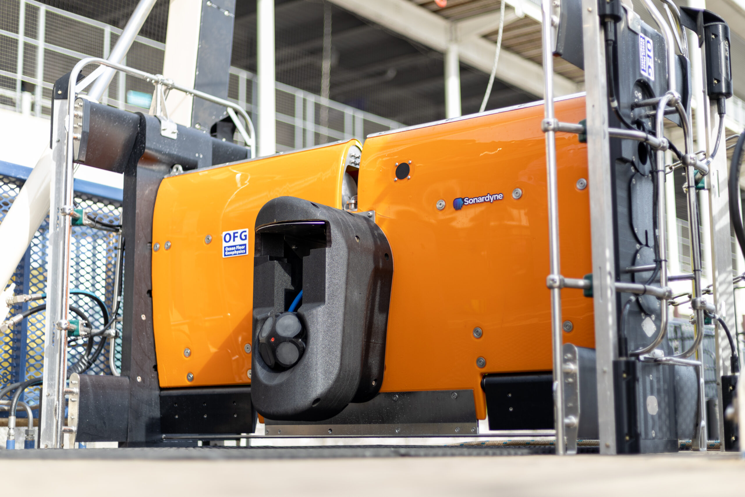
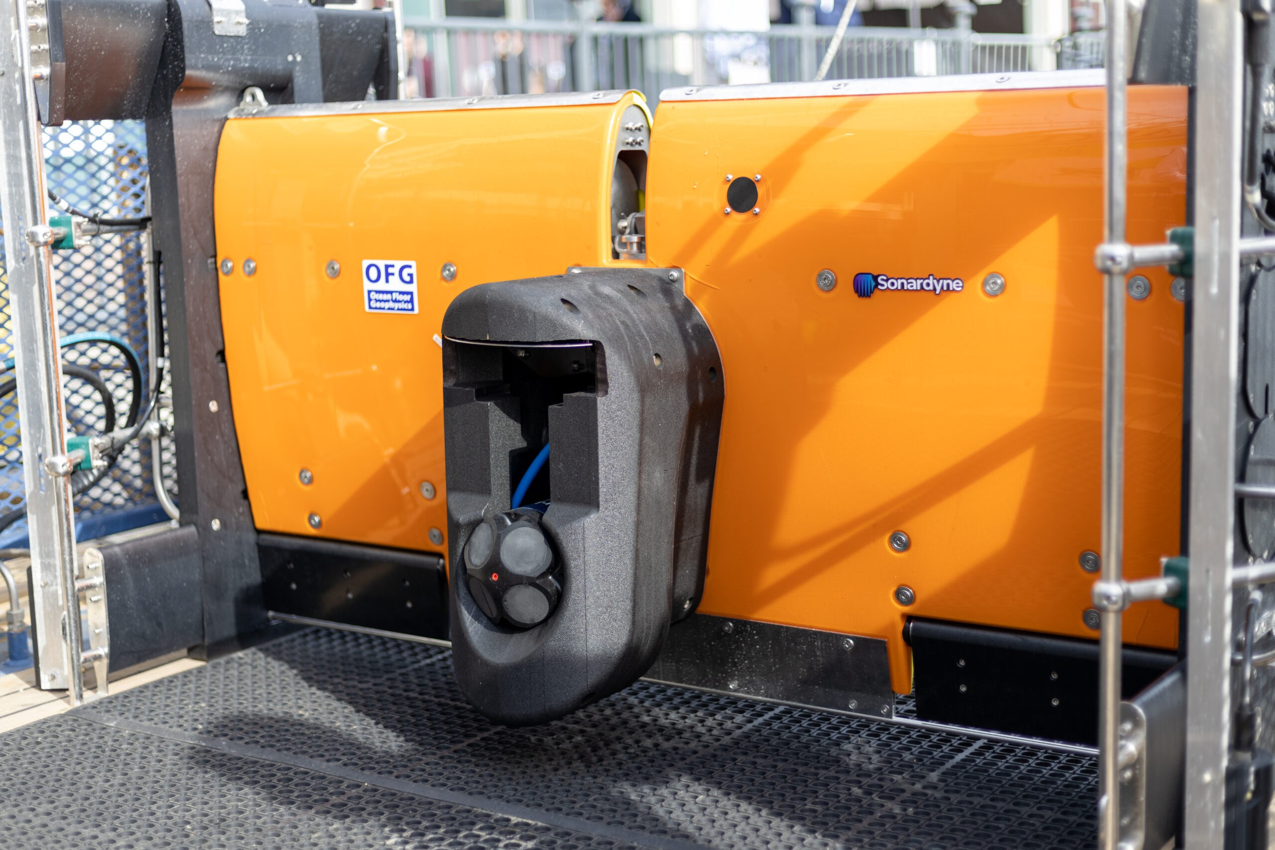
Seabed surveys are now on the critical path towards meeting global renewable energy generation targets. That’s why Ocean Floor Geophysics are working on ways to improve how pipelines and cables are detected and monitored. Our positioning and navigation technologies were used to support a demonstration of their Hypermag gradiometer with Covelya Group company EIVA.
The Challenge
Detecting cables or pipelines on the seabed and checking or monitoring cable depth are essential requirements in the development and management of most offshore energy projects. With a global target of 80 GW of offshore wind to be built annually by 2030, these tasks are also now on the critical path.
Magnetometers or gradiometers (comprising an in-line array of magnetometers) are a key tool for these operations. Accurately knowing the position of these instruments in the water throughout a survey ensures that target detection resolution is as high as possible. So, Canada-based Ocean Floor Geophysics’ (OFG) has developed the Hypermag gradiometer.
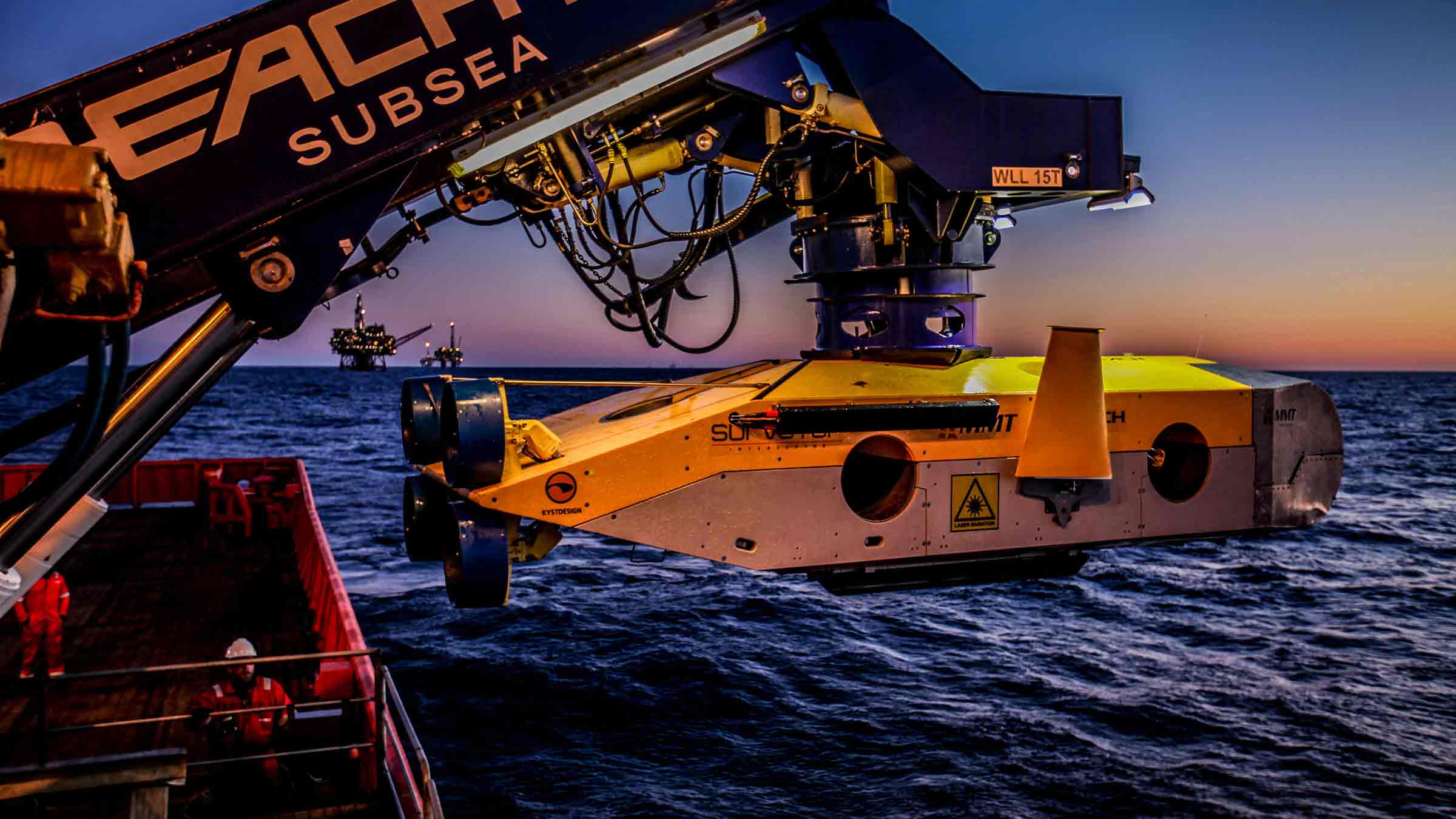
Rather than towing a magnetometer or gradiometer from a vessel or ROV, OFG’s Hypermag has been designed with multiple vector magnetometers installed in a scalable array that can be integrated directly onto a remotely operated towed vehicle (ROTV), such as EIVA’s ScanFish. This removes any positional uncertainties seen when using a layback offset when towing a magnetic sensor. The multi-vector gradiometer could then acquire compensated magnetic data in real-time
OFG possesses advanced multiphysics capability, particularly in fusing acoustic data with magnetic and electromagnetic field data, in this case magnetic field interpretation across multiple three-vector sensors. The team, therefore, required optimum shallow water positioning of the ROTV to demonstrate the gradiometer at its highest capability. “A high-quality, accurate navigation solution is a key component in achieving the full potential from our next generation of magnetic vector gradiometer sensors,” says OFG CEO Matthew Kowalczyk. “In shallow water environments, such as near-shore windfarms and UXO survey sites, it can also be one of the most difficult datasets to produce.”


The solution
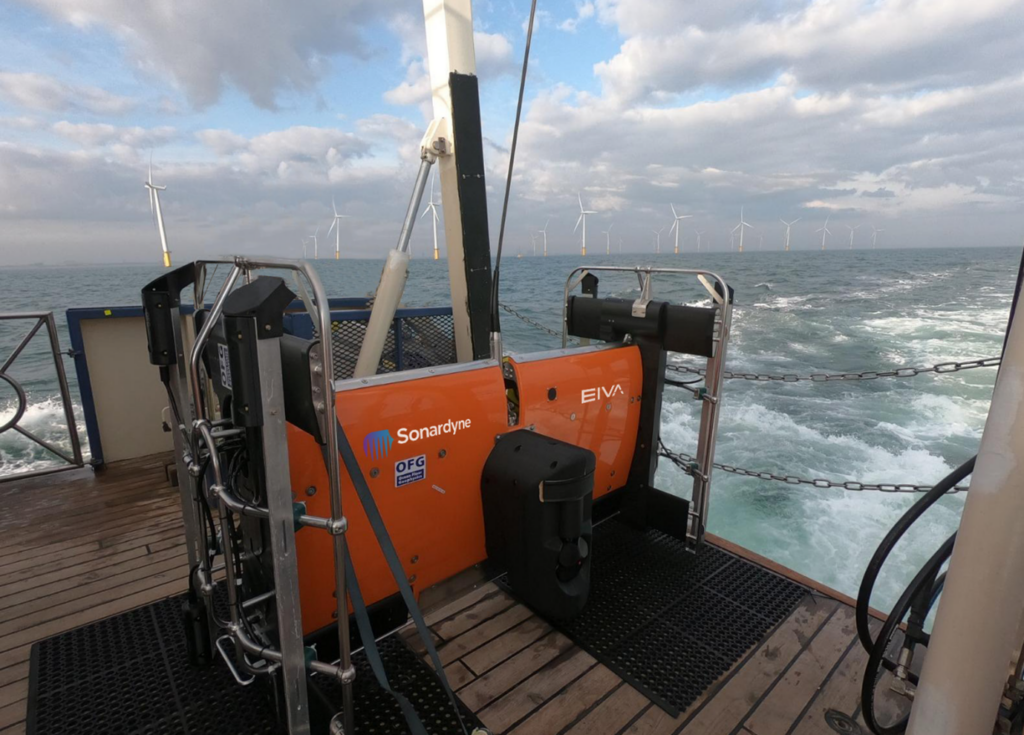
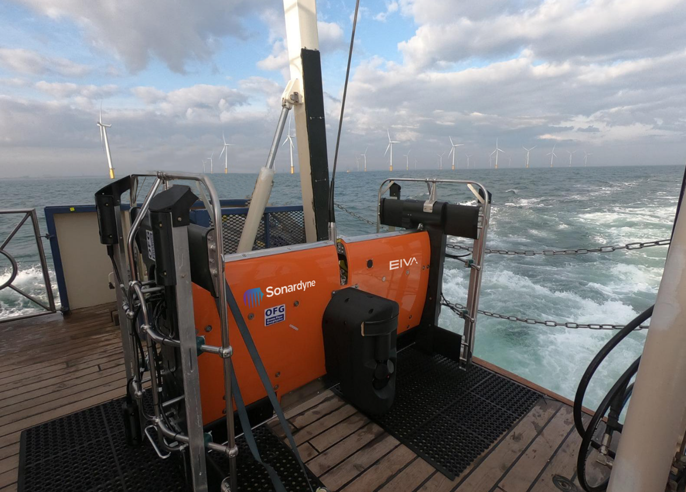
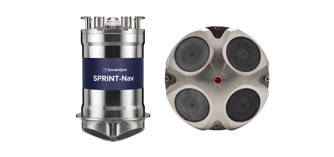
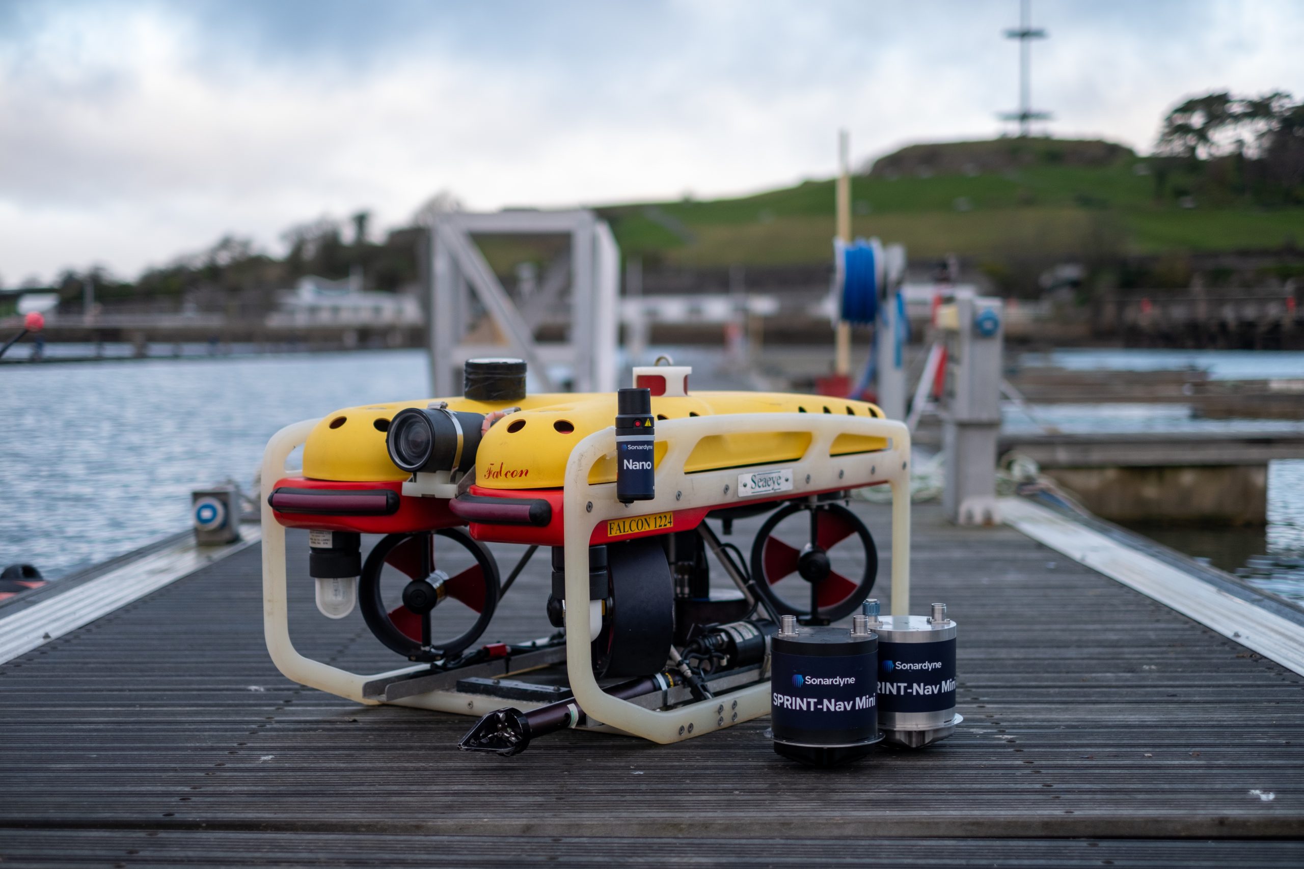
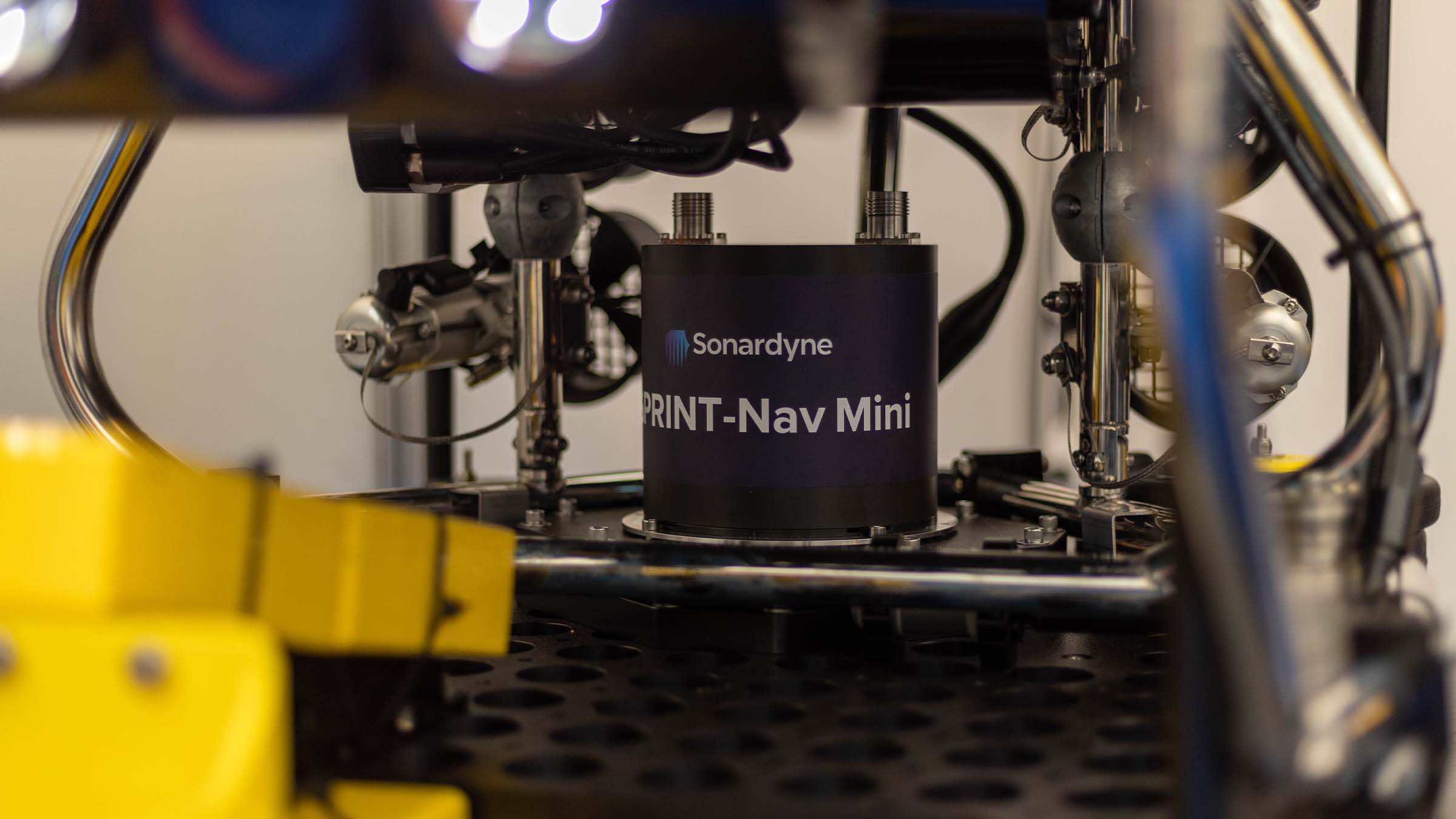
Covelya Group companies EIVA and Sonardyne supported a demonstration of the Hypermag in the vicinity of a wind farm in the North Sea. EIVA provided ScanFish support, including integration of the Hypermag configuration, a Norbit multibeam and a NaviPac software solution. Sonardyne provided a SPRINT-Nav Mini INS system alongside Ranger 2 equipped with a Gyro USBL transceiver, providing OFG with comprehensive position and behaviour accuracy of the ScanFish platform and it’s offset Hypermag sensors.
The SPRINT-Nav Mini Navigator is our smallest form factor hybrid navigation instrument, combining an INS, AHRS, Doppler velocity log (DVL) and pressure sensor.
By using this integrated INS system, updated by the Ranger 2 Gyro USBL, positioning errors or any erroneous USBL pings or dropouts could be mitigated. The INS can, in real-time, reject outliers in the data and output AHRS data, velocity, depth and altitude, as well as outputting real-world positional data in real-time, mitigating the need for post-processing. In addition, the SPRINT-Nav Mini could support multibeam data acquisition when a combined multibeam and magnetic gradiometer solution is used.
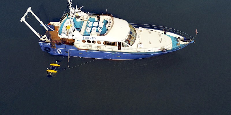
To put the approach to the test, a vessel of opportunity, the 22 m Marshall Art survey vessel, was mobilised. We used our Ranger 2 Gyro USBL system, which comes pre-calibrated, for easy mobilisation, with a Norbit iWBMSh multibeam echosounder (MBES) on Marshall Art providing RTK GNSS into the Gyro USBL.
On the ScanFish there were two OFG Hypermag panels, comprising a total of eight magnetometers, our SPRINT-Nav Mini Navigator, an omnidirectional Wideband Sub Mini 6+ transponder and a Norbit multibeam. An OceanEnviro fibreoptic winch system was installed on the vessel to tow the ScanFish. Orientation and position data was provided by the SPRINT-Nav Mini.
The results
“This was a great collaboration,” says Matthew Kowalczyk. “The combination of Sonardyne’s Ranger 2 Gyro USBL system and SPRINT-Nav Mini allowed us to quickly produce a navigation solution for the Hypermag system that exceeded our expectations.
“A high-quality navigation solution is necessary for achieving the full potential from our next generation of marine magnetic vector gradiometer sensors. Sonardyne’s support contributed to the trial’s overwhelming success.”
Another benefit of using SPRINT-Nav Mini on the ScanFish is that it can support its 3D steer algorithm, which can make surveying more efficient, reducing overall survey costs.
Pipelines and cables are often surveyed using a zig-zag pattern to decrease survey time. However, the most efficient way to survey a pipe would be to run parallel to the pipe, which EIVA 3D Steering allows with a suitable navigation solution because the position of the data measurement can be known with higher certainty.
Straight out of the box navigational enhancement for offshore out of straightness surveys
Fugro are already delivering safer, faster and more sustainable offshore operations – as you may have read in our previous case study about the Mini-Ranger 2 USBL system being used to support ROV operations from a USV. Working with us, Fugro are continuing their pioneering remote operations with their fleet of uncrewed surface vessels (USVs) deploying remotely operated vehicles (ROVs) – changing the game for offshore infrastructure surveys. Read on to see how our SPRINT-Nav Mini is being used to enhance multibeam echosounder (MBES) on Fugro’s remote operations, providing incredible results.
The challenge
Out of straightness (OOS) surveys are used for acquiring information about the vertical and horizontal configuration of offshore pipelines. They provide operators with information on the presence or otherwise of buckles and bending in a pipeline, which may be engineered or not, and require monitoring during the operational life of the pipeline or flowline asset.
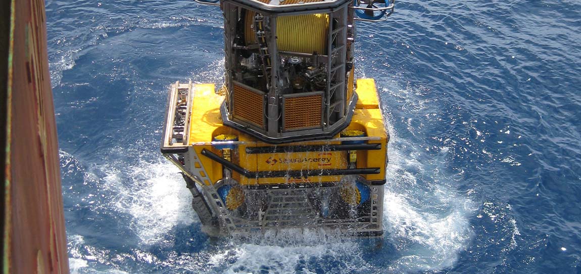
Fugro have been conducting OOS surveys on pipelines for major energy companies in Australia for many years. These surveys were conducted using a Norbit WBMS Narrow Multibeam echo sounder mounted on a Fugro inspection class ROV deployed from Fugro’s 12m Blue Essence® USVs, Maali and Kwilena.
ROV missions along pipelines can be erratic and unreliable due to the distance between the transceiver (USV) and transponder (ROV) when using just USBL positioning. For Fugro’s OOS survey customers, highly accurate data is essential. This has led to their requirement for the highest accuracy navigation and imaging available to the small ROV.
Fugro set us the challenge to provide a navigation solution that would enable the customer requirements of high-quality data using a small ROV. We worked with Fugro to trial SPRINT-Nav Mini and demonstrate the capabilities of the system.
The solution
SPRINT-Nav Mini is the world’s smallest hybrid navigator, combining INS, DVL, AHRS and a pressure sensor in one factory calibrated unit. SPRINT-Nav Mini’s true north seeking gyrocompass means that it delivers reliable surface and subsea navigation. Adding this navigation capability to any marine robotic system allows users more control and turns their vehicles into far more accurate inspection and survey platforms.
With everything you need for navigation packed into a single low Size, Weight and Power (SWaP) package, SPRINT-Nav Mini is simple to integrate into any marine vehicle along with other payload sensors, like Fugro’s MBES. Its impressive precision of 0.05% of distance travelled accuracy on a typical survey alongside our revised heading, pitch and roll specification means that advanced mapping is now possible on smaller platforms deployed from USVs.
“SPRINT-Nav Mini is becoming increasingly vital for geophysical survey operations where SWaP is critical. Users need accurate and high output rate navigation streams for real-time compensation of imaging sensors.” Says John Houlder, INS Product Manager, Sonardyne, “SPRINT-Nav Mini provides robust real-time results that are improved even further once post-processed in our Janus software.”
After demonstrating SPRINT-Nav Mini’s capabilities, Fugro purchased the system and have been deploying it on their inspection ROV, which in turn is deployed from the Blue Essence® USV. With the Fugro team’s input we have been able to revise our specification for SPRINT-Nav Mini, improving its suitability for use with MBES on geophysical survey. These revisions include:
Pitch and Roll: 0.1 to 0.02° RMS
Heading: 0.15 to 0.1° RMS


The results
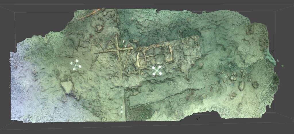
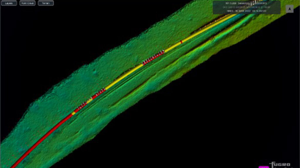
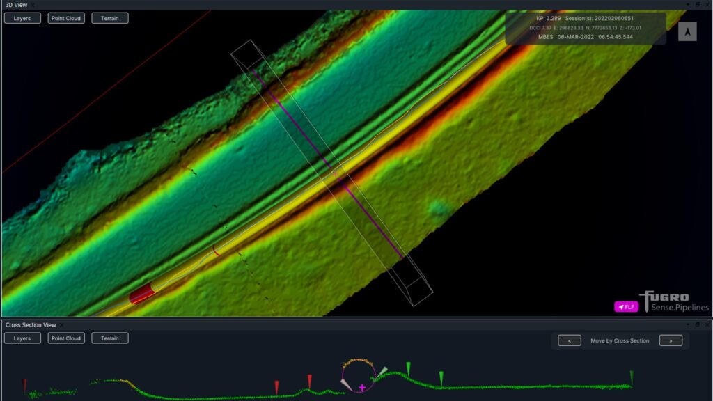
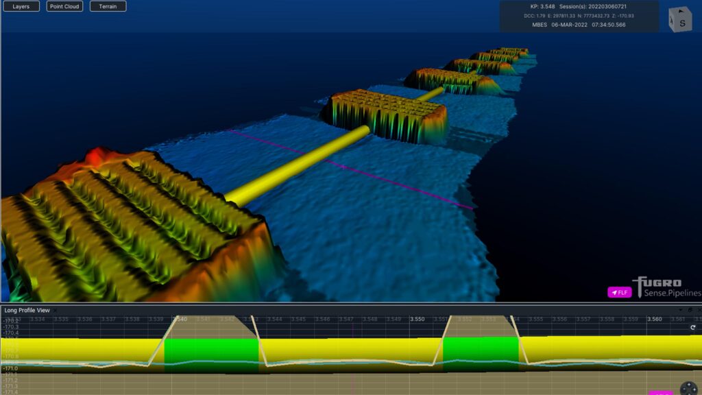
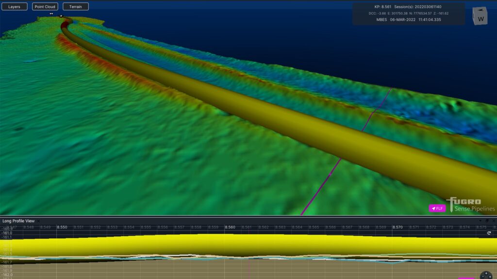
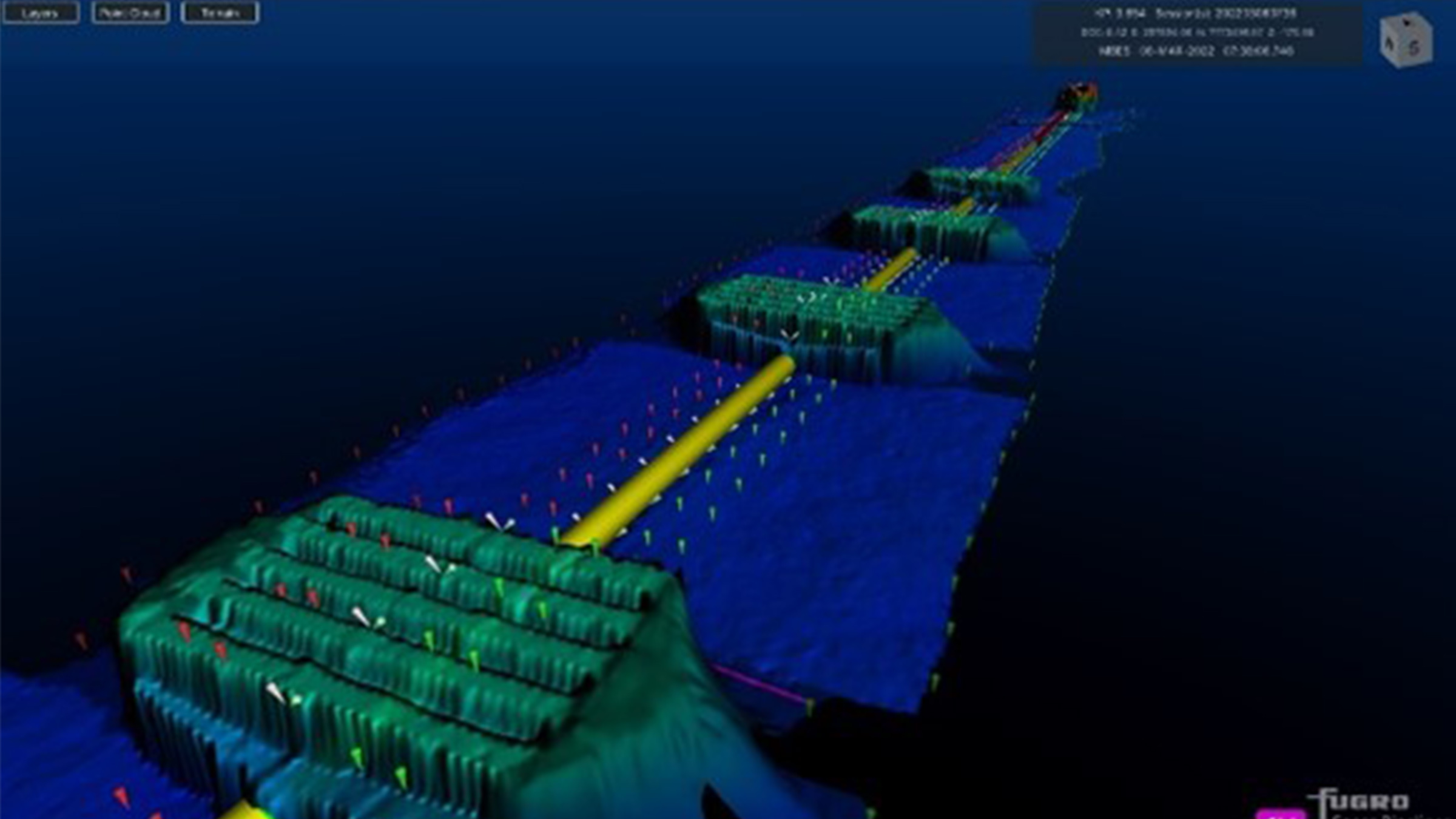
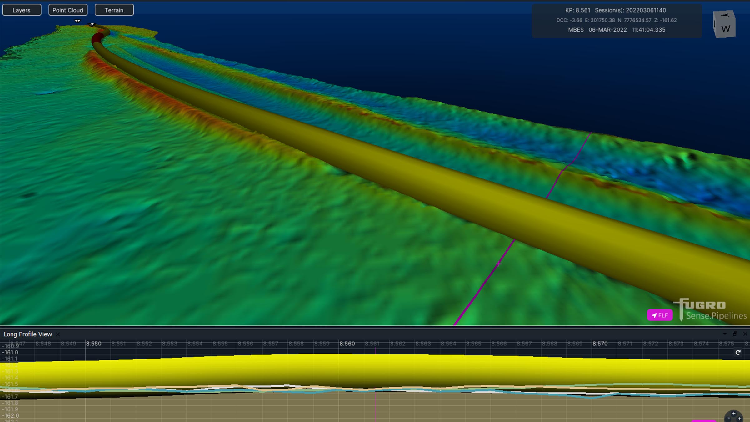
Fugro utilise SPRINT-Nav Mini data within the ROV command and control software, Starfix® navigation, including their Camblock Vision based augmented reality system, and for processing MBES data. In the case of MBES processing, they are also conducting pipeline OOS surveys to a maximum depth of 200 metres.
The images below show some example data Fugro has gathered with MBES positioned using SPRINT-Nav Mini and post processed with our Janus software. Janus is our quality control and INS post processing software. It allows quick and easy data editing, post-processing and data export. Find out more about Janus here
If your offshore operations are also reliant on fast, efficient and accurate data to keep your business competitive in an ever-changing marketplace, take a look at our full range of navigational products here.
Overview
The industry standard for seismic surveys
Positioning rope connected seismic nodes or ocean bottom cables accurately and efficiently is often accomplished in challenging underwater environments. Our shallow and deep water positioning systems are scalable for small or large surveys and have an impressive global track record of use in the offshore seismic industry.
Designed to work in any depth
From less than 1 m in the transition and surf zones to 3000 m for ultra-deep-water seismic applications.
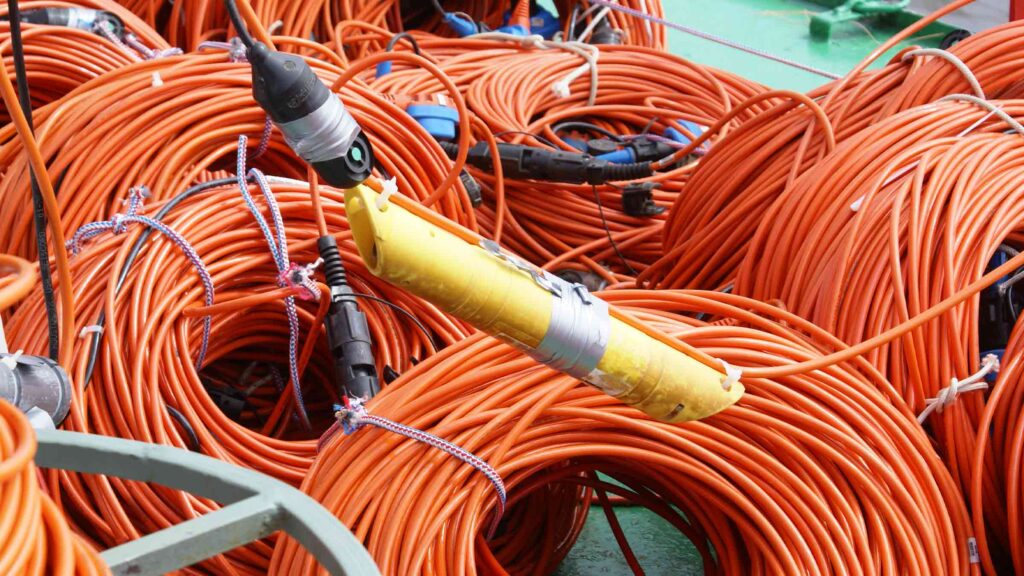
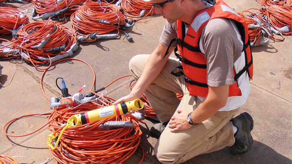
Our shallow and deep rated acoustic positioning systems improve the speed, accuracy and efficiency of positioning seabed marine seismic nodes and cables, enabling the positioning of thousands of transponders in parallel with deployment and shooting operations.
The system uses a network of low cost, rugged transponders that can withstand fast deployment through mechanical ‘squirters’ to provide users with an efficient method of collecting the positions of thousands of seabed nodes in real-time.
A typical system comprises of acoustic positioning transponders attached to the seismic node or cable and a vessel or USV based acoustic range only or full USBL transceiver interfaced to a PC running our HydroPos seismic positioning control software application. Third party software applications that incorporate an acoustic control module can also be used with the system.
Once the nodes are deployed on the seabed, the system precisely measures the acoustic range (distance) or 3D position (USBL) from a surface transceiver on the pinging vessel to each transponder to enable its exact position to be established. The range and USBL positioning processes are more accurate than traditional first break techniques, 1-2 m absolute, and can either be conducted during node or cable deployment operations or later whilst shooting.
Configurations
Shallow water (range only or full USBL)
Uses HF band vessel or USV-mounted TZT or HPT2000 USBL system with Transition Zone Transponders and LRTs attached to seismic nodes or ocean bottom cable receivers. Offers ranging precision of better than 50 mm in up to 500 m water depth.
Deep water (range only or full USBL)
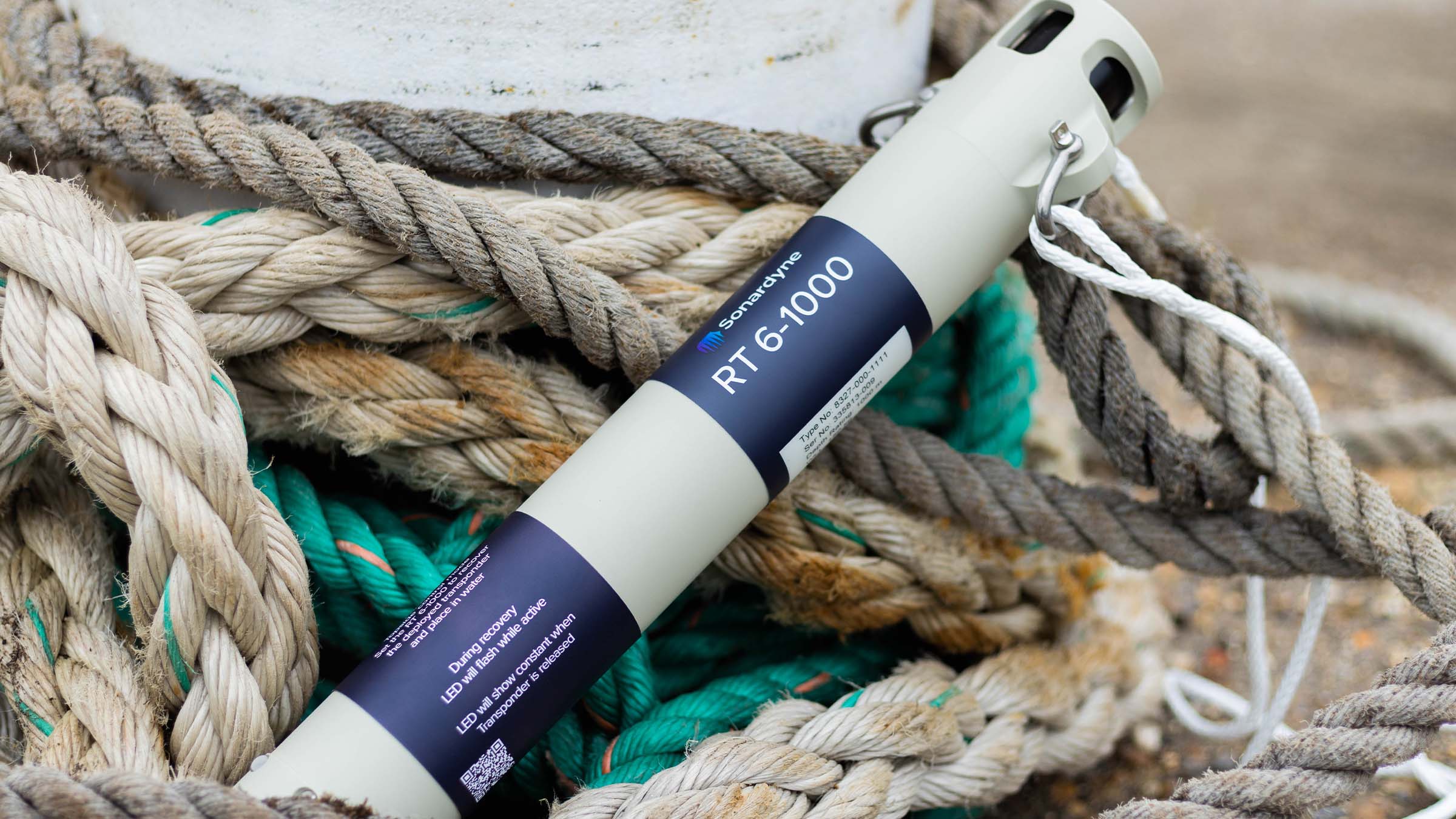
Uses MF band vessel or USV-mounted TZT or HPT 5000 USBL system with SST 6 and RT6-1000 transponders. Offers ranging precision of better than 15 mm in up to 3,000 m water depth.
OEM integration
Get all the benefits of of our deep water system but with an OEM version of our SST 6 integrated in to your seismic node.
At a glance
- Enables you to position thousands of nodes or cabled seismic receivers in real-time
- Operational in 1 to 3,000 m of water
- Uses low cost acoustic transponders and acoustic releases
- Scalable for both small and large surveys
- Scalable for both small and large surveys
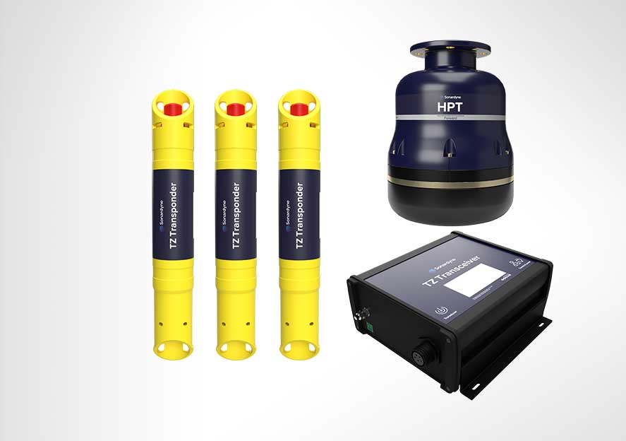
Transponders
The transponders developed for the system are small and lightweight and are proven to withstand the demanding and varied operational environment of surveys.
Standard features of the popular Type 7815 TZ Transponder include a depth rating of 500 metres, a unique acoustic ‘address’ enabling thousands of units to be laid in a single deployment and battery voltage monitoring to allow users to better plan their maintenance schedules. TZ Transponders operate in the HF band.
The LRT is a release transponder option for this system. It incorporates an acoustic release mechanism and is typically used at rope or cable ends to aid recovery of seabed seismic equipment after shooting is complete.
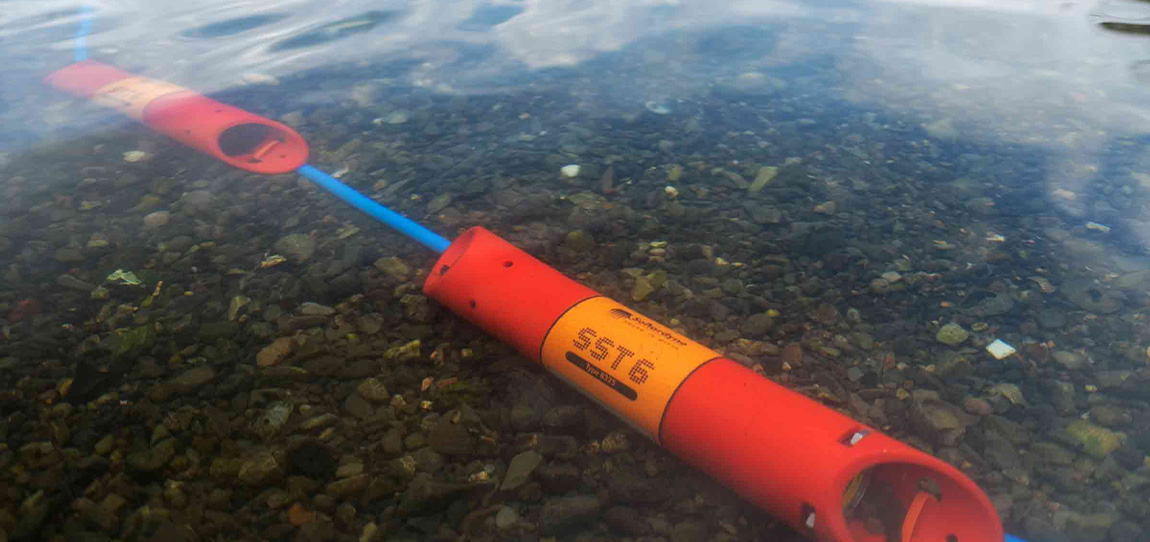
SST 6 incorporates our Wideband 2 digital acoustic signal processing architecture ensures robust positioning performance with high levels of ranging precision. It can be provided in 1,000m and 3,000m depth rated housings and is fitted with a handy Near Field Communications (NFC) link as standard for programming and battery status checking.
RT 6-1000 is a release transponder option for this system. It incorporates an acoustic release mechanism and is typically used at rope or cable ends to aid recovery of seabed seismic equipment after shooting is complete.
Both SST 6 and RT 6-1000 are MF band transponders, compatible with our family of Ranger USBL acoustic positioning systems.
Transceivers
Two surface transceiver options are available for this system. TZ Transceiver (TZT) is small and lightweight making it perfect for use vessels-of-opportunity and uncrewed surface vessels which are increasingly being used in support of offshore seismic operations. It can operate in the HF or MF frequency band.
TZT is able to interrogate and calculate acoustic ranges to nine TZ Transponders or 95 SST 6 transponders at a time.
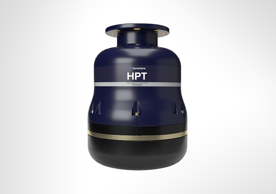
HPT 2000 (HF) and HPT 5000 (MF) are USBL transceivers configured to measure range and bearing to TZ Transponders and SST 6 transponders respectively. They are particularly well suited to high elevation tracking scenarios and offers true simultaneous tracking of multiple transponders providing superior position update rates.
Our team is here to advise you which configuration of transponders and transceivers your offshore seismic positioning system should be configured with to meet to operational requirements.


Design
• Incorporates almost three decades of operational and client feedback
• Supports new generation (6G) and legacy hardware transponders inventories – thousands in service globally
• Suitable for small survey vessel or USV operations; safer, greener, lower cost
• Works with all major seismic software platforms
• Optional asset tracking with transponder RFID technology
Performance
• Operate in <1 m to 500 m water depth • Operates in with Sonardyne HF (35-55 kHz) or MF (19-34 kHz) bands • Up to 18 month battery life for TZ/OBC transponders • Position 3,600 transponders in real time • Range-range or range-bearing (USBL) operating configurations available
Datasheets
Manuals and quick start guides
Overview
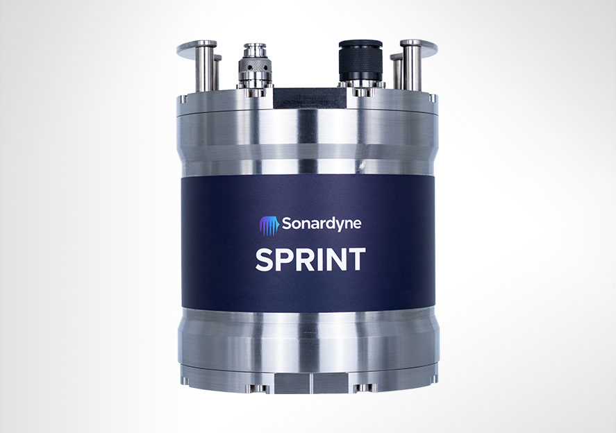
Revolutionising your subsea navigation
SPRINT is the acoustically aided subsea inertial navigation system (INS) for all your ROV, towed platforms and AUV operations. Giving you flexibility, cost-effectiveness and ease of use, it embodies our commitment to bringing you innovation in subsea navigation.
Get the SPRINT advantage
SPRINT gives you:
- Robust performance in challenging subsea conditions
- High-precision outputs for enhanced vehicle control
- Instantaneous start-up without lengthy alignment periods
- Seamless integration with your existing equipment
SPRINT optimises acoustic aiding data from USBL, LBL, Doppler Velocity Log (DVL) and pressure sensors, improving position accuracy, precision, reliability, and integrity. It extends the operating limits of your vessel’s USBL and enhances LBL efficiency by enabling sparse seabed transponder arrays. All while reducing operational time and vessel costs.
Choose your SPRINT
- SPRINT 300: Perfect for dual ROV and survey use, standalone ROV guidance, and mid-water station keeping. It’s the most cost-effective subsea INS available, with less than 0.1° Sec Lat Heading accuracy.
- SPRINT 500: Ideal for your demanding multibeam survey operations. Supports tightly integrated sparse LBL range aiding from Sonardyne 6G transponders, with automatic pressure and swell compensation.
- SPRINT 700: Our highest-performance INS system, designed for your most challenging subsea survey tasks. Supports mobile laser mapping and acoustic inertial metrology with tight integration to Sonardyne acoustics.
The technology
Inertial navigation is inherently self-contained and robust with very good short term accuracy, but it can drift over time. Therefore, the SPRINT INS is supported by complementary acoustic positioning to provide long term accuracy and robustness. This significantly reduces operational delays during periods of challenging subsea acoustic conditions such as aeration and noise. The precision and update rate of the output allows greater subsea vehicle control and makes SPRINT suitable for ROV station keeping.
SPRINT shares a hardware platform with our Lodestar AHRS and runs both AHRS and INS algorithms concurrently. This allows instant INS start or restart upon receiving a position update, eliminating the lengthy ‘alignment’ period common in other systems. The system monitors AHRS and INS orientation separately to assess its health. All calculations are performed internally, protecting against communication issues. The system maintains a 15-day backup of navigation and raw data on an onboard SD card, while topside software concurrently logs all data, ensuring data integrity.
DVL and AHRS/INS
Our Syrinx DVL provides tight beam-level aiding to SPRINT, giving superior positioning performance even with partial beam availability. Standalone 3rd generation SPRINT and Syrinx DVL can be joined together for pre-calibrated, interchangeable use, or combined into the compact SPRINT-Nav unit. This integrated solution, optionally including an internal pressure sensor, is suitable for various ROV and survey tasks. The combined unit features depth-rated water blocks for each transducer to protect the internal components and when supplied together typically doesn’t require re-export licensing, simplifying your shipping logistics.


Performance
• Heading accuracy 0.02° (secant latitude)
• 0.01° Pitch/Roll accuracy
• 0.03% Typical survey accuracy
• USBL/LBL aided: 4.5 x precision improvement
• USBL/LBL and DVL aided: 6 to 13 x precision improvement
• INS Aiding supported: USBL, depth, DVL, zero velocity, manual position, LBL (position), GNSS
Design
• Titanium housing construction
• Provides concurrent AHRS and INS capability for dual use
• In field remote performance upgrades: Yes
• Onboard data storage and battery backup to ride through brown outs
• Navigation outputs: position, depth, attitude, velocity, accelerations, rotations
Ownership
• Warranty: 1 year return to Sonardyne service centre
• ITAR Controlled: No
• UK Export Licence: Yes
• What’s in the box: SPRINT, mounting plate, test lead and cable tail, Fusion 2 software
Typical applications
• ROV and towfish positioning
• Hydrographic and multibeam survey
• ROV DP including mid-water station keeping
• Offshore construction; trenching, as-laid, OOS, touchdown monitoring, structure placement
Specifications
| Performance | SPRINT 300 | SPRINT 500 | SPRINT 700 | |
|---|---|---|---|---|
| Heading | 0.05° secant latitude | 0.04° secant latitude | 0.02° secant latitude | |
| INS initialisation | Instantaneous | Instantaneous | Instantaneous | |
| Roll and pitch | 0.01° | 0.01° | 0.01° | |
| INS aiding supported | USBL, Depth, DVL, Zero Velocity, Manual Position, LBL, GNSS | USBL, Depth, DVL, Zero Velocity, Manual Position, LBL, GNSS | USBL, Depth, DVL, Zero Velocity, Manual Position, LBL, GNSS | |
| USBL/LBL aided | 3x precision improvement | 3.5x precision improvement | 4.5x precision improvement | |
| USBL/LBL and DVL aided | 3 to 7 x precision improvement | 4 to 10 x precision improvement | 6 to 13 x precision improvement | |
| LBL/DVL aided | 3 cm confined area, 20 cm wide area (dynamic) | 3 cm confined area, 20 cm wide area (dynamic) | 3 cm confined area, 20 cm wide area (dynamic) | |
| DVL aided | Typical survey | 0.05% | 0.03% | 0.02% |
| Distance from origin | 0.15% | 0.10% | 0.08% | |
| DVL aiding loss/drift | 1.2 m over 1 minute, 5 m over 2 minutes |
0.8 m over 1 minute, 3.2 m over 2 minutes |
<0.5 m over 1 minute, 2 m over 2 minutes |
|
| Station keeping | <1 m over 24 hours (Syrinx DVL) | <1 m over 24 hours (Syrinx DVL) | <1 m over 24 hours (Syrinx DVL) | |
| Power | ||||
| Power requirement | 20–50 V dc, 15 W nominal (35 W maximum) | 20–50 V dc, 15 W nominal (35 W maximum) | 20–50 V dc, 15 W nominal (35 W maximum) | |
| Power pass through | 3x for external aiding sensors (up to 3 A per sensor) | 3x for external aiding sensors (up to 3 A per sensor) | 3x for external aiding sensors (up to 3 A per sensor) | |
| Internal battery backup | Li-ion/5 minutes | Li-ion/5 minutes | Li-ion/5 minutes | |
| Data/Comms | ||||
| Data storage | 8 GB internal memory | 8 GB internal memory | 8 GB internal memory | |
| Serial ports/protocol | 4x RS232 or RS485 | 4x RS232 or RS485 | 4x RS232 or RS485 | |
| Other ports | Ethernet, 4x Triggers | Ethernet, 4x Triggers | Ethernet, 4x Triggers | |
| Output rate | Up to 100 Hz | Up to 100 Hz | Up to 100 Hz | |
| Mechanical | ||||
| Connector options | 4x Seacon/Seanet 1x Seacon/Seanet |
4x Seacon/Seanet 1x Seacon/Seanet |
4x Seacon/Seanet 1x Seacon/Seanet |
|
| Mechanical construction | Titanium | Titanium | Titanium | |
| Dimensions (diameter x height) |
4,000 m (Seacon) | 205 x 260 mm | 205 x 260 mm | 205 x 260 mm |
| 6,000 m (Seacon) | 205 x 280 mm | 205 x 280 mm | 205 x 280 mm | |
| 4,000 m (Seanet) | 205 x 250 mm | 205 x 250 mm | 205 x 250 mm | |
| Weight in air/water | 4,000 m | 18.5/11.5 kg | 18.5/11.5 kg | 18.5/11.5 kg |
| 6,000 m | 22/14 kg | 22/14 kg | 22/14 kg | |
| Environmental | ||||
| Depth rating | 4,000/6,000 m | 4,000/6,000 m | 4,000/6,000 m | |
| Operating temperature | -20 to +55°C | -20 to +55°C | -20 to +55°C | |
| Storage temperature | -20 to +60°C | -20 to +60°C | -20 to +60°C | |
| Shock rating | 22 g, 11 ms half sine | 22 g, 11 ms half sine | 22 g, 11 ms half sine |
Frequently asked questions
How to mount and extract an ISO image
SPRINT, SPRINT-Nav, Lodestar and Lodestar-Nav troubleshooting
How to calculate the heading accuracy of a SPRINT
How to use Fusion 2 LBL and INS dongles
Can I power my subsea instruments with Lodestar or SPRINT?
How do I mate and calibrate a SPRINT or Lodestar to my Syrinx DVL?
How sparse is a sparse LBL array?
What cables do I need for my SPRINT?
How do I mate and calibrate a DVL to my SPRINT?
What software and firmware is compatible with SPRINT and Fusion 2 Systems?
What’s the difference between FOG and RLG?
What does Vehicle and IMU frame of reference mean?
ROV operational procedure for SPRINT-Nav
Can I input an external depth sensor into SPRINT or SPRINT-Nav?
How to plan my sparse LBL array (guidance note)
How do I calibrate my sparse LBL array?
How do I set up SPRINT-Nav in Fusion 2?
How to interface Ranger 2 into a 3rd party survey system
STP files
Software and firmware
Software and control hardware
Top tips
Datasheets
Manuals and quick start guides
Overview
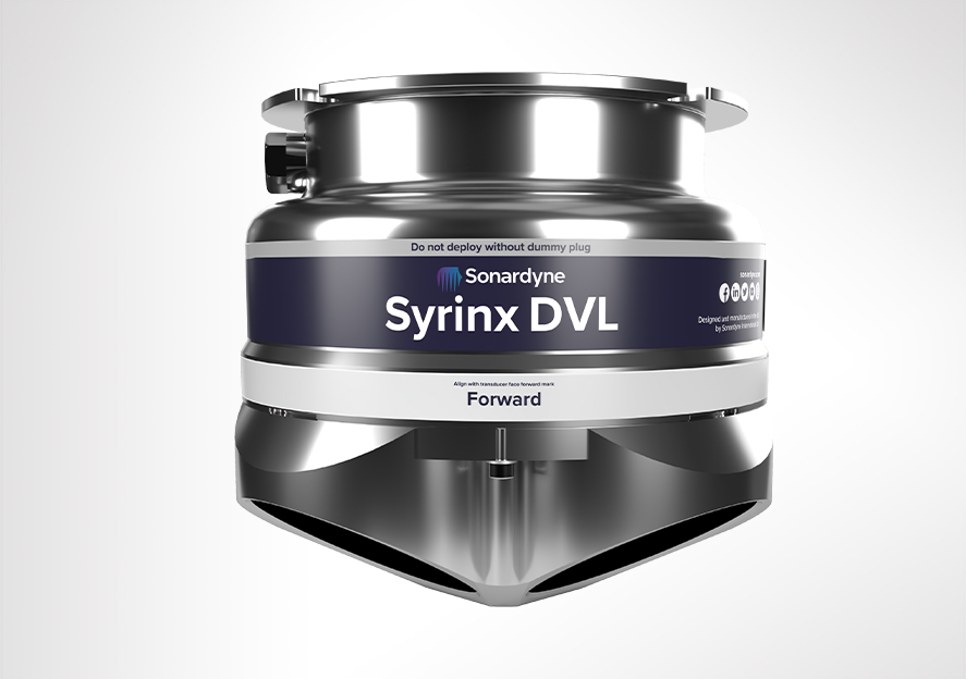
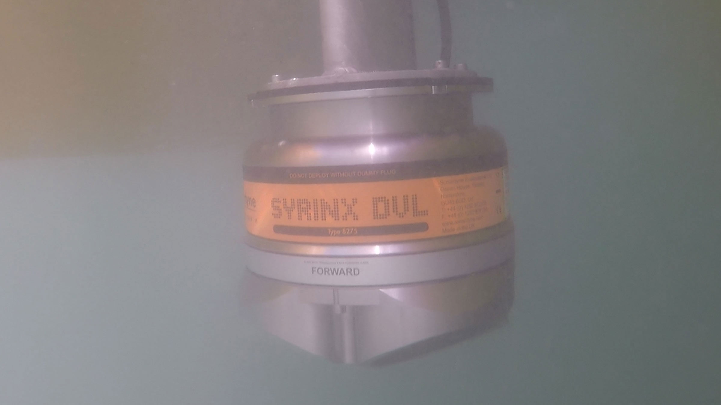
Navigate further, profile deeper
Welcome to the future of your underwater navigation and profiling with Syrinx DVL. A dynamic solution combining a high-performance Doppler Velocity Log (DVL) with an integrated Acoustic Doppler Current Profiler (ADCP), designed to elevate your underwater operations.
Engineered for AUVs, ROVs, and vessels, Syrinx is your reliable companion in the depths. Whether you’re looking for a standalone DVL, an ADCP, or a fully integrated navigation system, Syrinx delivers it all in one powerful package.
Designed and manufactured entirely in the UK, Syrinx is a class leading DVL for surface and subsea vehicles, available in two frequencies: 600 kHz or 400 kHz for higher altitude tracking up to 230 m. Syrinx variants combine high resolution and high altitude tracking, in single, easy to install navigation instruments. Its adaptive bottom lock technology provides consistency and reliability over challenging and changing topography, working at an altitude higher than 85% of the world’s subsea infrastructure. This reduces the amount of time a vehicle must dive on free inertial.
If your mission requires water profiling, Syrinx’s highly capable ADCP mode enables both navigation and profiling without the need for separate instrument, saving you cost and payload.
When tightly integrated with Sonardyne’s SPRINT INS, unmatched DVL-aided navigation can be achieved. This allows for enhanced performance through optimisation of beam-level data passed between Syrinx and SPRINT to aid velocity prediction and outlier rejection, with positioning able to continue even if one or two DVL beams are unavailable. For the ultimate integration Syrinx and SPRINT are also available as a single combined unit with integral pressure sensor. SPRINT-Nav is one of the smallest inertial DVL instruments available on the market suitable for almost any ROV and survey task.
Why Syrinx?
- Unmatched Versatility: Use Syrinx as a DVL, ADCP, or both simultaneously. You decide how to harness its power.
- Deep-Water Performance: Maintain solid bottom lock up to 230 m, with 4,000 m depth rating as standard.
- Adaptive Technology: Our smart bottom lock ensures reliable navigation across varied seabed types.
- Dual-Frequency Options: Choose between 400 kHz for extended range or 600 kHz for high resolution.
- Seamless Integration: Syrinx works harmoniously with our SPRINT INS for unparalleled navigation accuracy.
- Efficiency: Combine navigation and water profiling in one instrument, saving you space and resources.
- Reliability: Individually replaceable transducers to minimise downtime.
- Adaptability: Available in 4,000 m, 6,000 m and OEM versions to suit your specific needs.
- User-Friendly: Web-based System Manager for easy configuration and control.
- Compatibility: Fits existing mounting arrangements and supports various data formats for smooth integration.
Dive deep, control smart
Syrinx runs an embedded system manager using a web browser, eliminating the need to install dedicated PC software. This allows configuration and testing of Syrinx prior to deployment, control during subsea operations and visualisation of the navigation data.
The hardware and vehicle interfacing are easy to install, set up and use. It’s compatible with DVL/ADCP mounting arrangements from other vendors so you shouldn’t need to modify your subsea vehicles to upgrade to Syrinx. PD0, PD3, PD4, PD6, PD13 telegrams are supported for integration to third party navigation systems.
A 4,000 m rated titanium housing is supplied as standard to meet the requirements of work-class ROVs. 6,000 m and OEM (no housing) versions are also available.
Syrinx’s transducers have been designed, built and tested in-house to provide maximum performance, and can be individually replaced, reducing ownership costs and repair time. The entire array is water blocked meaning that should damage occur to the transducer array, the unit’s electronics are isolated from water ingress.
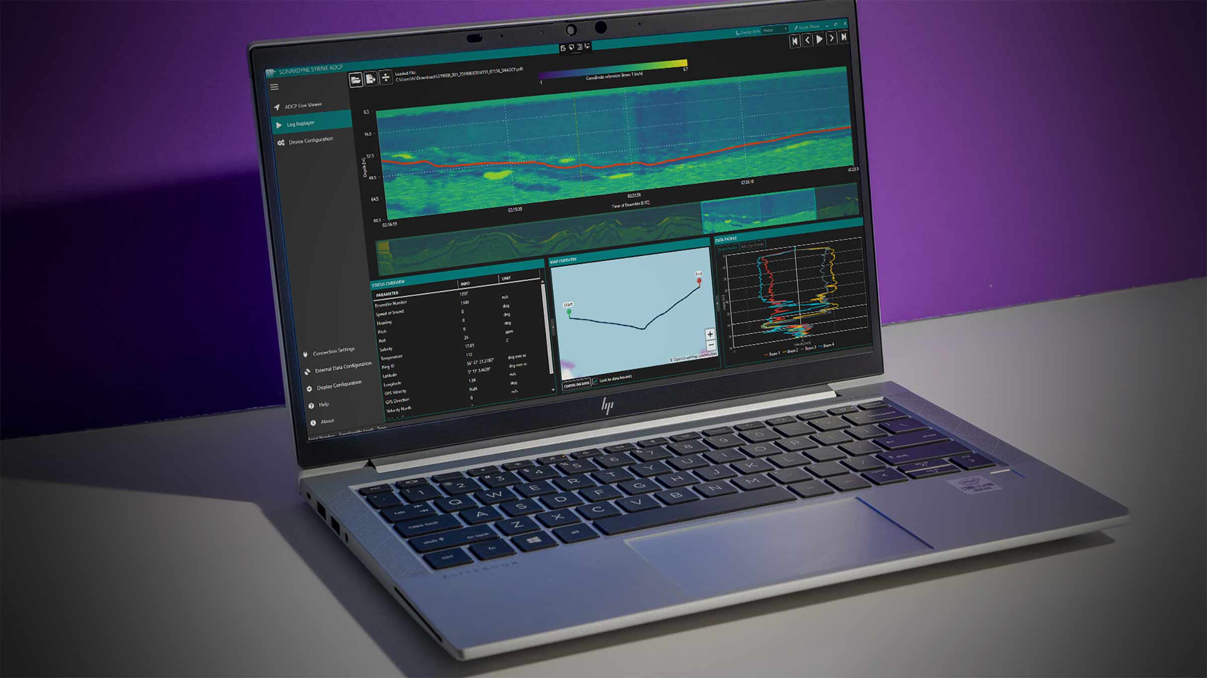
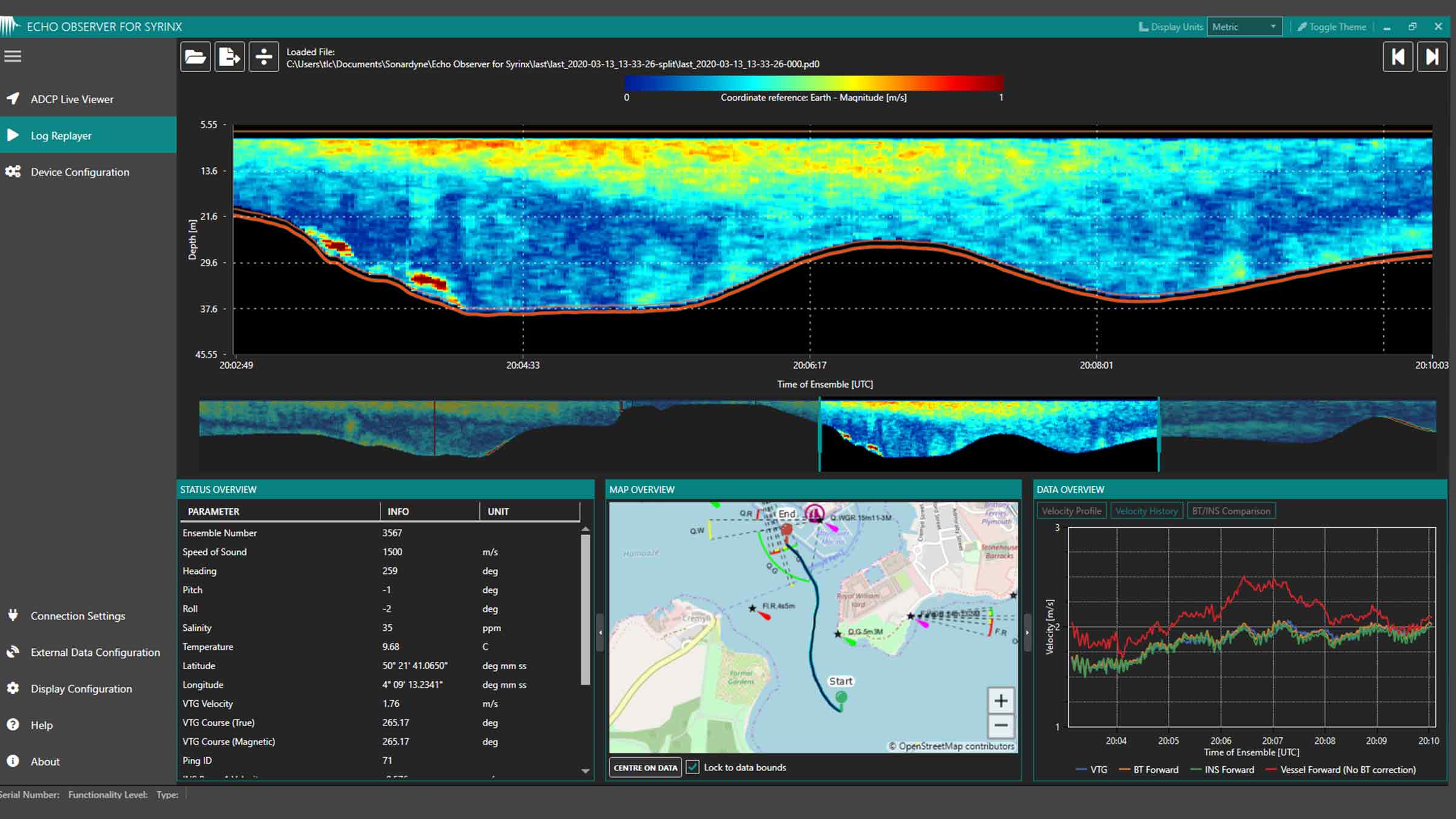
Echo Observer for Syrinx (EOS)
EOS is a software application for Syrinx and SPRINT-Nav systems which allows ADCP data to be viewed, quality controlled, logged and then exported. This standalone application is compatible with Windows 7 or 10 and requires only modest processing resources.
EOS provides an intuitive interface to Syrinx, allowing the device to be configured over Serial port or Ethernet with a quick setup procedure for ADCP measurements. You can immediately view the profile data and make any necessary adjustments before committing to a long-term deployment.
Once initial data inspection has been completed, EOS provides the link to the onward data processing chain: Industry-standard PD0 data can be exported as comma-separated variable (CSV) files, ideal for importing into Excel or Matlab for analysis and post-processing. The exported PD0 data can be tailored to match your analysis needs, such as specific portions of the water column, or a favoured frame of reference.
Specific sections of the PD0 data can be omitted in CSV export if they are not relevant to your analysis, reducing file size and therefore processing time. Echo Observer for Syrinx is included with the ADCP functionality upgrade for both Syrinx and SPRINT-Nav.
Experience the Syrinx DVL advantage
Whether you’re navigating an AUV through complex underwater terrain or precisely positioning an ROV for critical operations, Syrinx provides the accuracy and reliability you need. Our adaptive technology keeps you on track over challenging topography, reducing reliance on inertial navigation.
Ready to transform your underwater operations? Let’s collaborate to integrate Syrinx into your systems and unlock new possibilities in subsea exploration and work. Connect with our team today!


Performance
• 0.4 /230 m min/max altitude
• 0.4–120 m ADCP profile range
• >10 m/s velocity range (DVL)
• 0.01cm/s velocity resolution (DVL)
• Up to ±8.4 m/s ±0.4% of measured value (ADCP along-beam)
Design
• Titanium housing as standard; OEM option
• Replaceable transducers; water block array
• Onboard web UI for setup and configuration.
• Dedicated software for ADCP features
• Max 204 mm x 225 mm, 8.2 kg weight in water (6,000 m version)
Ownership
• Warranty: 1 year return to Sonardyne service centre
• ITAR Controlled: No
• UK Export Licence: Required
• What’s in the box: Syrinx DVL/ADCP and QuickStart guide, EOS software (optional)
Acosutic
• 400 or 600 kHz frequency
• 4-beam array @ 30 degree angles
• Up to 25 kHz DVL ping rate
• Up to 4 Hz ADCP ping rate (optional mode)
Specifications
| Feature | 8275-4531/6531 600 kHz | 8275-4561 400 kHz | |
|---|---|---|---|
| Operating Frequency | 600 kHz | 400 kHz | |
| Bottom Velocity – Single Ping Precision (Standard Deviation @ 1 m/s) | ±0.22 cm/s | ±0.28 cm/s | |
| Long Term Accuracy | ±0.12% ±0.1 cm/s | ±0.22% ±0.1 cm/s | |
| Minimum/Maximum Altitude | 0.4/175 m | 0.4/230 m | |
| Velocity Range | >10 m/s | >10 m/s | |
| Velocity Resolution | 0.01 cm/s | 0.01 cm/s | |
| Data Output Rate | 25 Hz maximum | 25 Hz maximum | |
| Water Reference Velocity | Accuracy | ±0.2% ±0.1 cm/s | ±0.2% ±0.1 cm/s |
| Layer Size | Selectable | Selectable | |
| Minimum/Maximum Range | 0.4/80 m | 0.4/120 m | |
| ADCP | Profiling Range | 0.4–80 m | 0.4–120 m |
| Velocity Range & RMS (Along Beam) | Up to ±5.6 m/s ±0.4% of measured value | Up to ±8.4 m/s ±0.4% of measured value | |
| Maximum Number of Cells | 255 | 255 | |
| Maximum Ping Rate – ADCP | 4 Hz | 4 Hz | |
| Maximum Ping Rate – DVL + ADCP | 2.5 Hz | 2.5 Hz | |
| Beam Width | ±1.0° | ±1.3° | |
| Beam Angle | 30° | 30° | |
| Transmit Source Level (dB re 1 µPa @ 1 m) | 217 dB (maximum) | 217 dB (maximum) | |
| Sensors | Temperature | -5 to 40°C | -5 to 40°C |
| Pitch/Roll (Optional) | ±0.5° | ±0.5° | |
| Pressure (Optional) | ±0.1% full scale | ±0.1% full scale | |
| Configuration (Array) | 4-beam array @ 30° beam angles | 4-beam array @ 30° beam angles | |
| Communication and Logging | Communications | Dual RS232, multi-port Ethernet (TCP & UDP) | Dual RS232, multi-port Ethernet (TCP & UDP) |
| Trigger Inputs | 3–12 V rising or falling edge configurable | 3–12 V rising or falling edge configurable | |
| Internal Logging | 32 GB internal memory | 32 GB internal memory | |
| Output Telegrams | Sonardyne proprietary, PD0, PD3, PD4, PD6, PD13, SDDBT Simultaneous telegram output |
Sonardyne proprietary, PD0, PD3, PD4, PD6, PD13, SDDBT Simultaneous telegram output |
|
| Voltage (dc Input) | 24 V (±10%) | 24 V (±10%) | |
| Average Power (Typical) | 10 W nominal | 10 W nominal | |
| Depth Rating | 4,000 or 6,000 m array | 4,000 or 6,000 m array | |
| Operating Temperature | -5 to 55°C | -5 to 55°C | |
| Storage Temperature | -20 to 55°C | -20 to 55°C | |
| Mechanical Construction | Titanium | Titanium | |
| Connector Type | Subconn | Subconn | |
| Dimensions (Height x Diameter) | 4000 m | 189 x 225 mm | 189 x 225 mm |
| 6000 m | 204 x 225 mm | n/a | |
| Weight in Air/Water | 4000 m | 12.0/9.1 kg | 11.3/8.5 kg |
| 6000 m | 14.4/10.9 kg | n/a |
Frequently asked questions
What is PD0?
What is a DVL and how does it work?
How do I mate and calibrate a DVL to my Lodestar?
How do I mate and calibrate a SPRINT or Lodestar to my Syrinx DVL?
What interference might I get between Syrinx DVL and the other acoustic equipment on my vehicle?
What is the maximum seabed slope that I can still bottom track?
How to correct for speed of sound
Can I externally trigger Syrinx DVL?
What is the maximum rate that I can ping?
What are the maximum and minimum velocities that Syrinx DVL can detect?
What are the maximum and minimum altitudes that Syrinx DVL will operate?
How do I mate and calibrate a DVL to my SPRINT?
How do I install a firmware update to Syrinx DVL?
How to download files from Syrinx DVL
DVL mounting considerations for ROVs and AUVs
What DVL messages are supported?
SPRINT-Nav Maintenance Schedule
STP files
Software and firmware
Top tips
Manuals and quick start guides
Technical bulletin
Overview
Perfect fit and precision
The perfect balance between size and performance, SPRINT-Nav Mini offers robust underwater and subsea navigation. It adds precision and reach to your operations. Your all-in-one vessel and marine robotics navigation instrument with real word results you can really on. It replaces the need for separate AHRS, DVL, INS and depth sensors.
SPRINT-Nav Mini fuses AHRS, DVL, INS and depth data into a single, lightweight instrument, giving you fast, precise and robust navigation, guidance and control information. There’s less cabling and fewer connectors to keep check of too. Not only is it simpler to mobilise, it’s also cheaper than the four sensors it replaces.
The prefect package for when you need reliable performance
Subsea navigation
Measuring just 213 mm in height (only fractionally taller than some competing DVL-only instruments), 148 mm in diameter and weighing in at approximately 3.6 kg in air for the 300 m rated unit – or 7.1 kg for the 4,000 m depth version , SPRINT-Nav Mini packs a big punch for all your underwater navigation ocean robot applications.
It’s powered by the same hybrid acoustic-inertial navigation algorithm you’ll find inside our established SPRINT-Nav family. This combines the strengths of all its sensors to provide robust, precise and accurate outputs. It continues to work even in challenging environments providing a continuous stream of positions, orientation, velocities, depth and altitude at up to 200 updates per second.
Ready to go – Pre-calibrated
Your SPRINT-Nav Mini arrives pre-calibrated, meaning there is no need to manoeuvre your vehicle every time the unit is mobilised. SPRINT-Nav Mini does the thinking for you, all in a single plug-and-play unit. Turn it on, give it a latitude, and away you go.
Despite its small size, it’s still a true north seeking gyrocompass which won’t drift over time unlike MEMS-based systems. The output can be fed directly to your own (or a third party) user interface or vehicle control software. The simple web user interface makes setup and configuration painless. It could not be any simpler.
Need to operate from coastal waters or around offshore structures? Not a problem! Low power and small, SPRINT-Nav Mini is ideal for installing on all size ROVs or USVs undertaking missions, even in GNSS-denied environments.
Conducting marine research on a restricted budget? Let us help… Because it’s lower cost than the four separate sensors it replaces, SPRINT-Nav Mini is the budget-friendly solution for your research platforms where funds need to stretch as far as possible.
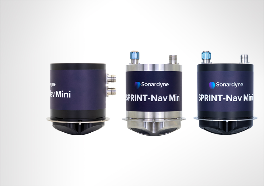
Available in two depth ratings, 300 m and 4,000 m. A side-connector option is also available, depth rated for 300 m and only 187 mm high, making it ideal for tight spaces on small platforms.
SPRINT-Nav Mini at a glance
- 213 mm tall by 148 mm in diameter all-in-one hybrid acoustic-inertial subsea navigator
- Hybrid DVL-INS synergies dramatically improve both robustness and performance compared with standalone instruments.
- Fly higher – 500 kHz DVL maintains bottom lock at up to 200 m altitude
- Replaces four separate instruments; AHRS, DVL, INS and pressure sensor – saving you cost, cabling and payload
- Easy to integrate, simple to operate, web UI for configuration


Discover more about SPRINT-Nav Mini
Straight out of the box navigational enhancement for offshore out of straightness surveys
Read moreDelivering subsea synergy in ORE inspections
Read moreMapping the future for seagrass beds in Plymouth Sound
Read moreOwnership
• What’s in the box: SPRINT-Nav Mini, mounting plate, test lead and cable tail
• Warranty: 1 year return to Sonardyne service centre
• ITAR Controlled: No
• UK Export License: Yes
Performance
• 300 m and 4,000 m depth rated options
• Provides 0.05% error for distance travelled
• Heading accuracy 0.5° secant latitude (0.1° Navigator variant)
• 0.02° Pitch/Roll accuracy
• 0.3/200 m min/max altitude
• 0.01% FS depth
• Up to 200 Hz output rate
• Better than 0.4 cm/s velocity precision (<2 m/s at 50 m altitude)
General
• Ideally suited for subsea vehicle guidance, control and navigation
• Size, weight and power optimised; perfect for all size vehicles
• Powered by our class-leading SPRINT hybrid navigation engine
• Cheaper than the four separate sensors it replaces
• Gyrocompass simplicity with hybrid acoustic-inertial navigation performance
Design
• 213 x 148 mm, 3.6 kg weight in air (300 m version), 7.1 kg (4000 m version)
• Acetal Copolymer (300 m) or Titanium (4000 m) housing construction
• Mounting plate, choice of top or bottom mounting location
• 14 pin and 7 pin Size A CRE connectors. Custom connectors on request
• Side-connector option
• User friendly web UI makes it easy to integrate and simple to operate
Specifications
| Performance | SPRINT-Nav Mini | |
|---|---|---|
| DVL Aided | Typical Survey | 0.05% |
| Distance from origin | 0.30% | |
| Altitude Min/Max | 0.3/200 m | |
| USBL & DVL Aided | Precision Improvement | Up to 5x better |
| Heading (Secant Latitude) with GNSS or USBL, and DVL | 0.10° | |
| Heading (Secant Latitude) with GNSS or USBL or DVL | 0.15° | |
| Roll and Pitch | 0.02° | |
| Angular Rate Range | ±450°/s | |
| Velocity Precision (<2 m/s at 50 m Altitude) | <0.4 cm/s | |
| Depth accuracy | 0.01% FS | |
| ADCP | Profiling range | 0.4–100 m |
| Velocity Range & RMS (along beam) | Up to ±6.7 m/s ±0.4% of measured value | |
| Maximum number of Cells | 255 | |
| Max Ping rate | 1 Hz | |
| Power Requirements | 24 V dc, 10 W nominal | |
| Data Storage | 32 GB internal memory | |
| Serial Ports/Protocol | 3x RS232 | |
| Interfaces | Ethernet, UDP/TCP, WebUI, 2x trigger inputs (1PPS/DVL trigger), NTP, ZDA + 1PPS out | |
| Mechanical Construction | 300 m | POM-C |
| 4,000 m | Titanium | |
| Dimensions (Diameter x Height) | Standard – 300 m | 148 x 213 mm |
| standard – 4,000 m | 148 x 213 mm | |
| Side connector – 300 m | 148 x 187 mm (174 x 187 including connector) | |
| Weight Air/Water | 300 m | 3.6/0.7 kg |
| 4,000 m | 7.1/4.2 kg | |
| Depth Rating | 300/4,000 m | |
| Operating Temperature | -5 to 50°C | |
| Storage Temperature | -25 to 55°C |